I always imagined that the current distribution to be rather good. I haven't given it much thought. My point about the PSU being a constant voltage source may back that up. The capacitance multiplier being a less than perfect one which might be the perfect compromise, It's often forgotten that the JLH has modest op amp abilities which make it rather better than tube designs of the SE type as regards hum.
The linear regulator, the capacitance multiplier and the SMPS operate in a mode that pulsates in time with the current consumption signal.
A high-capacity storage capacitor after the regulator brings the situation to a constant voltage source.
Unregulated power supplies with capacitive or inductive energy storage work differently. As an integrator with a large time constant.
A high-capacity storage capacitor after the regulator brings the situation to a constant voltage source.
Unregulated power supplies with capacitive or inductive energy storage work differently. As an integrator with a large time constant.
Last edited:
Hi Nigel!
Had to search the archives to find a Z30 circuit. Yes there is a lot wrong, but not everything. Last time I checked out a Z30 the output transistors used were oddities.
It simulates with D44H11's as fast output devices, still available last time I looked.
If the current regulator transistor in the CCs for the VAS stage is mounted on the heatsink then the quiescent current might just be controllable despite no emitter resistors.
I think Sinclair used under-spec'd OP transistors which gave it an unreliability reputation.
At what power level ?
I've been tesing at 3.1V RMS into 20 Ohms.
I posted some FFT plots earlier in the thread, and if I remember correctly H2 & H3 were around -90dB at 1W. This is with a PNP version from ZeroZone. Main thing to reduce the distortion was to find the optimum bias current, and adjusting the balance between the two resistors to the base of the 'current source' output transistor to optimize (AC) current sharing between the output transistors.
I have written about it before, and even posted a sim of the amp. The problem is to find something in this long thread..
Thanks, I remember seeing posts of your PNP version but didn't recall if you posted measurements. I'll use the Goog machine to find them.
It should be impossible to hear at this level. If a class AB we could infer the machine might have traits which give a sonic signature. When class A harder to believe.
Quite easy to hear in this case. The 'static headphones are wonderfully revealing of subtle diffferences. My son was up for Easter, brought his best dynamic 'phones along. He had never heard 'stats before and was blown away. Heard the same differences between amps that I did. Not subtle.
The Stax headphones most recently looked at are likely an ideal load for class AB. For a power supply class AB is an ideal load. It looks likely in this unique case class AB is unsubtly better.
I think I've already accepted that but am trying to save a dying patient before putting it down 🙂 Plus, this is partially a learning exercise for me.
I would reduce the JLH current to the minimum if using the Stax. They say you can't have too much of a good thing. When current be certain. I have a hunch 250 mA is enough for the sta. IM distortion might reduce.
I'll experiment with that. I tried going the other way, with 18V @ 1A bias, and saw minor improvements, but didn't try going lower.
john_ellis said:In the JLH, the power supply current largely follows the current in the upper output transistor, so it will increase for a + output and decrease for a - output.
That is my understand as well. I figgered we want the outputs to have gain linearity either side of the static bias point. So I tested the 15022 outputs at 100, 500, 1000, and 1500 mA to see if current gain was consistent, and it was. They were better than any of the 3055's in that respect.
Not sure that the envelope is as important as the actual signal frequency.On a complex musical signal, we will see a low frequency envelope modulated by the mid and high frequency components.
Graham Maynard might have been a little confused about "first cycle distortion" but he was right to recommend using 22mF output capacitors instead of the common 2.2mF (at the time).
There is a lot of Folklore with this. A very fast class AB should be better except there is more risk of getting it wrong. The JLH in theory is 20 dB better than we need.. They old world sound most likely IM distortion. If you think about it THD is like a 2D. If current is involved we get 3D.
I made a 6 watt SE valve amp with bootstrap CCS to the driver valve ( 2 valves ) 1% THD and 0.2% 1 watt. It was the least distorted sound I ever heard. I am not Dire Striates greatest fan until using it. So many layers. Real dynamics and micro detail. No negative feedback not even local. Positive feedback as said. Rather better than my friends 300B amp which sounds dark and false. He tried about 5 tubes for me. Kron were best. Mine EL34 or KT88. Almost triode ( 80% triode UL ). PSU MOSFET multiplier. That changed hum from -62 dBV to -88 dBV at output. -62 dBV was loud. 0.6 vrms in and about 7 Vrms out. I made a feedback circuit to bias the output tube grid. It might have given 8 watts. That gives cherry anodes on test signals but not music. Time constant needs to be carefully choose. I imagine that would be 50 mA music peak and 15 mA doing nothing. 24 mA in standard mode. I think I worked out the life of the tube should be longer if done with care. The idea was to be a 211 which was from that friend. 813 also. I prefer EL34 to most others.
Without the CCS 3 % THD. I used a MJE 350 as CCS as a reference. Results were identical to bootstrap CCS via the 16 ohm tap. The 80% triode UL was a spare tap for another tube. Boosted the sensitivity whilst not changing distortion style. Non loop feedback UL is an unusual and good idea. An LM317 current sink to the EL34 cathode was another reference.
The best amplifier I ever heard was a mildly upgraded Marantz model 9 from it's designer via Quad ESL63. Very like my own whilst being unfussy about load. The mods were capacitors and LM317 ripple rejector ( Described by Chuck Hollander ).
#7885 save a dying patient before putting it down - From a local forum: Simulators suggested using an inverted phase splitter stage. Just install PNP BD140 in place of BD139 (emitter up, collector down).
In front of it, add the usual cascade of the OE npn (emitter to ground, base to collector T1, collector to base BD140 and 10 kΩ to (+). It is said that distortions are reduced by an order of magnitude.
You may have to pick up resistors in the feedback and correction.
In front of it, add the usual cascade of the OE npn (emitter to ground, base to collector T1, collector to base BD140 and 10 kΩ to (+). It is said that distortions are reduced by an order of magnitude.
You may have to pick up resistors in the feedback and correction.
Last edited:
Agree - simulations show IMD down at 0.01% for 10kHz/11kHz input with 8.2k changed to 3.3k, BD139 with emitter grounded and BD140 driver, with 680 ohm resistor across base to emitter of BD140, collector of BD139 to base of BD140.
And that was with a 2N3055 (epi) device model, with its quite high gain-Ic roll-off.
Eliminates a large Vbe modulation across the 8.2k.
But question on stability - needs checking
And that was with a 2N3055 (epi) device model, with its quite high gain-Ic roll-off.
Eliminates a large Vbe modulation across the 8.2k.
But question on stability - needs checking
Last edited:
That configuration in the post above suffers latch-up on overload.
Needs optimising.
That sort of work is beyond my discrete paygrade at present.
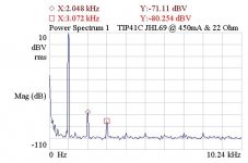
This is interesting. Ordered a couple months ago, just arrived today, a couple of the little TIP41C-based JLH boards from eBay:
Mini 1969 TIP41C 1 Channel Amplifier Assemble Board Pure Class A DC 12V-30V 24V | eBay
They cost less than $2.50 fully assembled. This is completely stock, as received (G=13). Supply is 15V with 450mA Ic, into 22 Ohm load. 1kHz distortion is even a tad better than the TO-3 version I've been tweaking on.
If the transistors are fakes, they're doing a pretty good job. As per Nigel's suggestion, I tried currents from 250mA and up, and distortion worsens. 450mA is the sweet spot, H3 starts rising at higher currents.
Clearly, there's no need to mess with the bigger TO-3 based boards at these power levels.
Attachments
These boards can handle higher voltages (up to 24V). The output transistors can be easily replaced with BD911, TIP3055, 5198, 5200, etc.(b-c-e)
You can use the SMPS laptop power supply 19v / 4.7a
You can use the SMPS laptop power supply 19v / 4.7a
Last edited:
I have some original 2SC3281, I may try those. Lower Hfe but more linear and faster. Would BD139 be a better driver? These boards have 41C's there too.
Last edited:
The driver can also be replaced. A 100pF B-C capacitor may be needed. Do not unsolder 1 transistor - the PCB tracks are damaged. You can bite off the leads and solder to them.
I tried to desolder on my TIP41C JLH boards and the PCB traces lifted. It is a good idea to just use cutters to remove the TO-92, for example, if you want to upgrade it.
The problem with BD139 is knowing if it's a good spec version.
ON Semi KSC2383YTA NPN Transistor, 1 A, 160 V, 3-Pin TO-92 | RS Components
ON Semi KSC2383YTA NPN Transistor, 1 A, 160 V, 3-Pin TO-92 | RS Components
I have concerns too about the BD139, but devices from On Semi and ST have measured as being high frequency.
My concern is that the fT line is missing from both ON Semi's and ST's datasheets. That is a concern as there are similar devices (BD239) which are epi base and were originally 3MHz-ish which are not suitable as drivers, but the ft is not mentioned on St's datasheet for that either.
Correction/edit: meant BD237, not BD239. But also true- no fT spec.
Last edited:
It's a fun little exercise to invent and build a fixture that lets you measure fT in your own workshop. Once you have it, you can contemplate testing 50 parts from the same manufacturing batch, and cherry-picking the fastest three units. Or even hand selecting "matched fT pairs" or quads.
I think the TTC004B is a good option - how much I measured Hfe even a little higher than the BD139 (I ordered 20 pcs npn-pnp from digikey)
It's a fun little exercise to invent and build a fixture that lets you measure fT in your own workshop.
As indeed I have done.
You don't need particularly high frequencies either. 1MHz sorts out the 100MHz versus 5MHz devices, 10MHz to confirm.
The point is though that not having ft on the datasheet leaves room for variations. We should not need to check!
That is the problem. As ON Semi has moved production lines around (Fairchild etc) that suggests there may be some lines which are used which do not have regular fT analysis capability. That would be odd, but a QA dept that does not have to check a spec. gets an easier time.
Last edited:
- Home
- Amplifiers
- Solid State
- JLH 10 Watt class A amplifier