For years I used Quad amplifiers. I considered them as a workhorses. This weird amplifier sold alongside the 303. It looks similar yet shares nothing in common. Of all Quad designs I like 303 best. 2/22 isn't really my cup of tea although an inspired design. 606 is OK. 405 is best as a mono-bloc. Quad have a spec sheet for that.
From memory Armstrong 621 had a Darlington VAS and sounded good.
From memory Armstrong 621 had a Darlington VAS and sounded good.
I am interested in the Quad 50, but I need details about the OPT.
I have biggish toroids for a 100 V system. Around 3 kilo, 1:5,5 with a center tap. Maybe i can use for something similar.
I have biggish toroids for a 100 V system. Around 3 kilo, 1:5,5 with a center tap. Maybe i can use for something similar.
I remember getting 7 kHz at - 3dB on a Vox AC 30 output transformer. When adding negative feedback it sounded horrible. I would imagine a standard toroid to be worse. The Vox was made by Avel and not a Beatles era type. Massive bass response.
I didn't read your question closely enough. Some 100V types will do as a tube output and even do UL. You might get a collector output design to work in transistor.
Cheap Output Transformers
I didn't read your question closely enough. Some 100V types will do as a tube output and even do UL. You might get a collector output design to work in transistor.
Cheap Output Transformers
Last edited:
On the topic of solid state amplifiers using transformers, the first step round here is S. Parker's Zero Feedback Impedance Amps
That uses Sowter iron. Hgh quality modern iron can also be obtained from Lundahl, Magnaquest, Tamura, Tango and O-netics. For a small fee 🙂
I had a Sowter transformer. I though a Danbury at far less money was better. Danbury alas are gone. Both used M6 alloy and the Danbury had equally good bass.
As Williamson pointed out the transformer must be doing the work and negative feedback if used carefully a bonus.
For simplicity I think tubes work more easily with transformers. EL34 is my preferred type. They work in Triode mode, UL, Pentode and G2 Triode. The latter is a weird idea that some think better. EL34 would work in Walker Quad UL as used by Trilogy amplifiers. G3 triode also as G3 is available which is rare. RH34 is a fascinating design.
JLH had a Williamson amplifier that he wanted to clone in transistor. The Williamson came at the beginning of the use of ultra linear operation circa 1947, it wasn't UL in the early form. Williamson was 19 when he designed it. He is said to have designed the Quad valve amplifier and most likely the ESL 57 speaker. Alan Blumlein probably invented UL in 1935 ( not Walker nor Hafller ). It was found that the pentode or beam tetrode amplification curves could be combined with the triode curves to make a more linear curve. Rather remarkably the pentode and triode were simultaneously in use in one device ( a transistor cascode can with difficulty mimic this ).This brought lower distortion and higher sensitivity without the horribly increasing anode impedance ( ra ) typical when a pentode. On paper negative feedback can transform a pentode into a triode. Alex Kitic in his RH series amplifier does just that. Interestingly Kitic uses transconductance as in JLH input to driver. This reduces the gain of the amplifier by about 4. He marks remarkable claims I wasn't able to duplicate. None the less an interesting design. 1938 RCA designs for 807 valve had similar despite Blumlein having proposed a more commercial design. It took Hafler 12 years to patent Blumlein's work. That's cheeky. Walker had to defend against that.
A transistor is roughly speaking a pentode like device with no similar feedback options. When people say a transistor is more linear I am left feeling I should say something. More linear being not very linear in reality. The JLH is an amplifier that can only be linear by using negative feedback. It is highly suitable for feedback which is a very big deal. I bet JLH must have spent hours getting the final design.
If you feel tempted to build a valve design you will be severely limited by output transformers. Forget all the load lines. Use a constant current sink and respect anode dissipation limits. 24 watts for an EL34 is about right. Manipulate grid stoppers and grid leaks using a spectrum analyser. After that it is quite easy if you don't try too hard to get the distortion very low. 0.2% is fine and 1% full power fine.
EL84 sounds much like a very good transistor and can be easily driven by op amps. That's a Frankenstein option many hate to use. It's most likely the best amplifiers you might easily own.
Triodes have higher ultimate damping factor due to a beneficial defect of triodes. Not all of the cathode electrons reach the anode. This makes for a distortion curve not unlike a JLH. It can be argued to be negative feedback inside the vacuum. A pentode tries to divert the returning electrons. A Beam tetrode is a patent bust to avoid paying Philips pentode royalties ( 1927 and 1935 ). Like transistors pentodes were the preferred option. Audio liked triodes. Some triodes like ECC81 seem very like transistors.
If you read JLH design notes this was the world he came from. Hopefully I didn't waste anyone's time reading this. The Valve Wizard is a good teacher.
http://www.audiodesignguide.com/New2A3/ETF06TS.pdf
unipolar - 0-(+18v), bipolar -12v-0-(+12v)
https://www.ebay.com/i/151388877083...g=2386202&algv=DefaultOrganic&brand=Unbranded
All from China.🙂
Consider the complete project. PCB + power supply + housing + ...
Hello,
Coming back from a previous thread here.
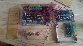
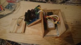
Following a generous tip by @OldDIY I assembled a JLH 3W kit from eBay to use as headphone amp. I power it with an external 12v linear power supply and audio comes from a good sounding 16bit DAC board. I built a couple of nice wooden boxes for the amp and the power supply, separated to avoid trafo interference–see pics if you like 🙂
Question: The JLH comes with variable resistor to adjust quiescent current, but I don't know in which point to set it. I've read that it's function is to avoid distortion and that it should be set according to needs. Currently they are passing 0.19A, measured with a multimeter in series at the input 12VCC. Transistors get very hot. When I lower it down transistors get cold and I can't notice much difference in the sound so far, but I don't know in what conditions to test. I also don't know how to use Ohm's law to calculate the ideal current point I need. My headphones are Sony MDR V6 (63ohm and 0,5W as far as I know) and input voltage DC 12v.
Many thanks in advance and wish everyone having a nice weekend.
Cheers from Berlin,
Domingo
Attachments
Hello Domingo!
At first glance, the radiators you used are too small. The area should be increased by 3-4 times (dimensions by 2 times). The operating temperature is no more than 60-70 "C. For a load of 60 ohms, the current could be reduced to 0.12-0.15 A / 12 v. If the pot adjustment range is not enough, you can increase the value of the upper constant resistor in the driver collector (220 ohm?) to 510 ohm - 1kom.
At first glance, the radiators you used are too small. The area should be increased by 3-4 times (dimensions by 2 times). The operating temperature is no more than 60-70 "C. For a load of 60 ohms, the current could be reduced to 0.12-0.15 A / 12 v. If the pot adjustment range is not enough, you can increase the value of the upper constant resistor in the driver collector (220 ohm?) to 510 ohm - 1kom.
Dear @OldDIY,
Thanks a lot for your response. I'll right away add more heat sinks, I think I can fit at least 4 or 6 more of those small aluminium pieces into my setup.
Regarding current, can I know how do you calculate the needed amps? According to Ohms equation I would need 0.19A (12v/63ohm). I like the idea of bringing it down to 15A or 12A, but I'm just curious why would the sweet point lie down there.
I'll post new pictures when heat sinks are installed 🙂
Regards,
Domingo
Hi Chumingo
With a very simplistic calculation: if your power supply is 12 volts, you will get a peak to peak swing of about 10 Volts before the output transistors saturate and it starts to clip and distort badly.
10 volts pk tp pk is approx (10/2)/1.4 =3.6 volts rms.
Assuming that you headphone impedance is 63 Ohms, to get 3.6 volts rms into 63 ohms, needs about 3.6/63 = 0.057 Amps.
I am not familiar with the headphone amp version, but the JLH usually needs about 0.7 of this as the quiescent current- which is 40mA - so round it up to 50mA.
Assuming that the output is set to be at the mid point of the power supply, (6 Volts) the idling dissipation in each output transistor is going to be about 12/2 Volts x 0.05 Amps =approx 300mW.
I would suggest you at least triple this for heatsink calculation purposes.
Check my maths - did I miss anything guys? 🙂
Happy listening
Mike
Last edited:
I think your calculations for minmum power with sensitive headphones are likely correct but there are headphones and other low power speaker applications that will actually demand more than milliwatts of power from something labelled as a headphone amplifier.
Generally, headphone applications today are designed with loads of overkill power, mainly because you can with the low cost parts available and also because it will look more substantial than some concoction of components that doesn't need to be any larger than a 9 volt battery. It would be more useful too, if it could drive small speakers such as those that came with your PC or are fitted in TVs. The popularity of the Chinese kits described as "JLH'69 headphone amplifiers" determines what most people will call them anyway.
Generally, headphone applications today are designed with loads of overkill power, mainly because you can with the low cost parts available and also because it will look more substantial than some concoction of components that doesn't need to be any larger than a 9 volt battery. It would be more useful too, if it could drive small speakers such as those that came with your PC or are fitted in TVs. The popularity of the Chinese kits described as "JLH'69 headphone amplifiers" determines what most people will call them anyway.
I think your calculations for minmum power with sensitive headphones are likely correct but there are headphones and other low power speaker applications that will actually demand more than milliwatts of power from something labelled as a headphone amplifier.
Exactly: Grado 60s can be driven off the smell of an oily rag. Stax electrostatics or the big Sennheiser cans need a solid watt per channel.
(Ironically, for such amps you need a "power soak" to drop 20 or 30db if you're going to use the grados with them without running out of volume knob sensitivity. Ask me how I know😡)
I think your calculations for minmum power with sensitive headphones are likely correct but there are headphones and other low power speaker applications that will actually demand more than milliwatts of power from something labelled as a headphone amplifier.
Generally, headphone applications today are designed with loads of overkill power, mainly because you can with the low cost parts available and also because it will look more substantial than some concoction of components that doesn't need to be any larger than a 9 volt battery. It would be more useful too, if it could drive small speakers such as those that came with your PC or are fitted in TVs. The popularity of the Chinese kits described as "JLH'69 headphone amplifiers" determines what most people will call them anyway.
Agreed, but now the original poster can do the maths themselves to get a sense of the power dissipation and heatsinking, which is where they had some doubt.
Interestingly, while typing this answer, the built-in spell checker flagged up 'maths' as a typo. I suppose it wanted the US colloquial version 'math'. GRRRRRR..
Cheers
Mike
Thanks for the answers to the previous post, it is very useful and comforting to receive some company and experienced knowledge in this adventure.
I'm a musician and sound recorder/mixer, so I'm very sensitive to sound or used to concentrate a lot in details, harmonies, noises, etc., very impressed with the performance of the JLH circuits. Their simplicity gives much more space, depth or almost analog quality than the devices I am used to work with (sound recorders and interfaces).
The challenge I'm facing now is not so much related to heat sinks, but audio levels and distortion (peak, overdrive-horrible distortion). I'm trying two boards that sound very different. The first is the one previously mentioned and suggested by @OldDIY long time ago, a 3W kit from eBay.
The second one is a very popular 5W board sold by many Chinese online stores
The sound that the second one gives in incredibly sharp and crisp, not in the sense that modern interfaces are but full of body, detail and continuity in the way different frequencies blend together. Much more clear and crisp than the eBay 3W. I guess the difference is because the circuit of the 2nd is simpler (and cheaper 😎), it has one less condenser at least. I couldn't relate their designs to Tim's JLH designs published around, but they are both quite similar.
The problem that I'm facing however is how to use these boards, especially the second one, as headphone amplifier (their size and 12VDC are convenient). When plugged directly to my DAC's line-out they sound too loud, distorting any sound over around -6dB (DAW's reading). I tried adjusting the bias variable resistor to the minimum, but had no success. I tried with quiescent currents down to 0.07A, which was the minimum allowed by the 3W board. The 5W board which I like more soundwise allows no less than 0.19A and distortion is still there, with similar peaks to the other one. I tried adding a 1000K resistor in parallel to the 220R next to the bias trimmer, but not even current consumption changed. The only way I managed to lower the levels and get a decent sound was adding a 600K resistor in parallel to the 2.7K resistor that goes after the emitter of the input PNP transistor, but I'm not sure what I'm I doing there. The volume decreases, no more peaks, but I'm not sure if the size of the resistance of the place where I'm placing it is decreasing sound quality as well...
I could always make it work adding a pot to lower the input audio signal coming from the DAC, but of course I would prefer to find a way to make the JLH "amplify less". Maybe replacing transistors?? Or some magic pill resistors? 🙂 Any information will be highly appreciated and regarded.
I can provide any information needed about the board. If needed I could even start transcribing the circuit.
Thanks a lot and stay healthy,
Domingo
To reduce the gain, try increasing the resistor in the emitter 1 of the transistor(pnp) to 510 ohms or more. To avoid damaging the PCB, bite off terminals of resistors removed and new solder to the conclusions of the former. Read # 7777 et seq.
Overload occurs 1) with excessive input voltage 2) with insufficient supply voltage.
You can safely increase the voltage to 24V, provided you use a large enough heatsink.
Single-ended amplifier 5W - is it a Nelson Pass mosfet amplifier?
Many variants of "JLH" amplifiers are produced in China🙂
Overload occurs 1) with excessive input voltage 2) with insufficient supply voltage.
You can safely increase the voltage to 24V, provided you use a large enough heatsink.
Single-ended amplifier 5W - is it a Nelson Pass mosfet amplifier?
Many variants of "JLH" amplifiers are produced in China🙂
Last edited:
The 5W amplifier I'm referring to has the same circuit than the one attached. Only two resistors are different: R9 is 39K instead of 27K; RL (in the output) is 100K instead of 10K. Other than that the circuit is the same. I wonder who designed it or where did the Chinese manufacturer take it from, it produces the kind of raw and direct pure sound I've been looking for.
Just to be sure @OldDIY, the resistor I have to increase in 510 Ohm to lower gain is R5? (2.7k in the diagram).
Just to be sure @OldDIY, the resistor I have to increase in 510 Ohm to lower gain is R5? (2.7k in the diagram).
Attachments
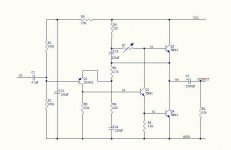
R4 (220) > Instability may occur after the change (optional).
The schemes are identical (JLH1969). The resistors you mentioned have no sacred meaning. R9+R1 defines DC voltage at the output (1/2 VDC).
The schemes are identical (JLH1969). The resistors you mentioned have no sacred meaning. R9+R1 defines DC voltage at the output (1/2 VDC).
Last edited:
I raise R4 from 220 to 900 ohm (680 ohm is the lowest resistor I have at hand now). No change in sound or distortion. I tried bigger ones going up to 5K and still nothing happens. Let me say that I'm trying this by temporarily pressing down different resistors over the existing one (in parallel), while hearing to my favourite tune. Might be that I need to find a smaller resistor to perceive any changes?
In the other hand, when I place the 680 Ohm over R5, so it raises from 2,7K to 3,4K, distortion is almost completely gone. As I increase the resistance of R5 distortion comes back increasingly, so I might need something slightly smaller there. I'm thinking of soldering a variable resistance in R5, that allows me to swing around it and find the right spot. Does this make any sense? Or is it a crazy idea and R5 should never be touched?
Thanks again for the invaluable help.
Domingo
- Home
- Amplifiers
- Solid State
- JLH 10 Watt class A amplifier