Hi Prasi
I've simulated your JLH circuit (using SIMETRIX) after installing the Cordell model for the MJL. You seem to have the right values of components and just before clipping I see something like a minimum current in the OP trannys of 65mA, and a standing current of 1.65A, which is just about right for 3A peak output. The output voltage peaks at 10.7V, I stopped short of actual clipping.
The current in the driver transistor is 27mA - but 54mA in the load/bootstrap resistors.
There are two points I was trying to make. One is that a small pot may not be able to handle the current - power was not the problem. If a 2.5k pot is rated at 1W then the maximum current expected is 20mA. So the bias current is higher than the track can handle. Whether a manufacturer would allow a higher current in a track if the total maximum dissipation is not exceeded I don't know, but I'm not sure that it would help much as tracks tend to be on insulating materials. Perhaps ceramic tracks with higher thermal conductivity might be used.
The second point is that with the Cordell model the gain of the MJL is 53 at peak output, which seems spot on for typical, but the lowest possible gain is (my estimate) 40 based on the specified minimum gain at 8A to the typical value in the datasheet. That would need 75mA peak and therefore a total load resistance of only 150 ohms. If the bootstrapped resistor is 50 ohms (47) then the pot, or pot plus series resistor, should be capable of going down to 100 ohms.
The other limit is the maximum gain which is (my estimate) perhaps 100, so the lowest current needed is going to be in the region of 30mA, requiring 380 ohms.
Putting these together suggests to me that you really need a 470 ohm pot rated for 75mA - which is a power dissipation of 2.6W but that would be an expensive pot! The power I see in the simulation I ran is just under 500mW, so we do need a high power pot depending on what ambient temperature is expected. A series resistor of 100 ohms (1W) would be my recommendation, but this is all theoretical. In practice you may be able to target a potentiometer to adjust the current over a narrower range than the worst case - yet again, manufacturers tend not to be too forthcoming with statistical data on their transistors. And maybe relieve some of the current using a parallel resistor.
Perhaps it would be a compromise to provide a spare set of resistor mounting positions both in series and parallel with the potentiometer (the series one being jumpered if not needed) and that might allow a 1W pot to be used but parallel resistors added if needed.
It would be appreciated if anyone can provide practical data!
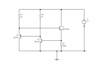
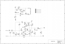
Perhaps the answer is to measure the gain of your output devices and select a resistor based on that. Here is a circuit which runs from a 5V power supply (old computer one perhaps) and sets the current to approx. 3A (adjustable with the emitter resistor).
Purpose of the additional PNP transistor is to allow the NPN to run at a more constant current without too much effect on the output transistor current.
Not shown, but an ammeter should be wired in series with the base of the OPT.
Not tested- just a proposal.
Purpose of the additional PNP transistor is to allow the NPN to run at a more constant current without too much effect on the output transistor current.
Not shown, but an ammeter should be wired in series with the base of the OPT.
Not tested- just a proposal.
Attachments
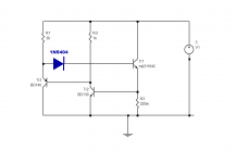
What's the VCB of Tr2? Seems pretty small. Maybe add a diode?
_
_
Attachments
Last edited:
The Vcb is not so important as Vce(sat). You might argue that any Vc below Vb will turn on the collector diode, but thanks to the exponential characteristic you can go a few 100mV before significant current flows.
The BD139 is specified because it has a hogh current rating and is only being used at a few mA. So I suggest there is no need for a diode. But feel free to add one if you are still concerned.
The BD139 is specified because it has a hogh current rating and is only being used at a few mA. So I suggest there is no need for a diode. But feel free to add one if you are still concerned.
Member
Joined 2009
Paid Member
If Vce(sat) is one of those parameters that varies due to wafer processing parameter spread, like hfe, it might be better practice to design with a margin of safety such as a diode?
I'd have agreed if transistors were still made in a bulk resistive collector wafer, but the epitaxy and low resistance substrates generally yield Vce(sat) of 0.3V for transistors like the old BFY51 at high currents, which also had a 0.1V Vce(sat) spec max at 10mA. The BD139 spec. is 0.5V at 500mA, so I do not think there is a problem - IF manufacturers keep to the (original) specs.
But manufacturing lines have swapped around so much recently it may be worth checking.
All of the BD139's I've measured would work no problem- now mostly ST and ON Semi.
But manufacturing lines have swapped around so much recently it may be worth checking.
All of the BD139's I've measured would work no problem- now mostly ST and ON Semi.
Last edited:
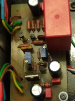
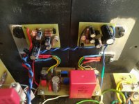
This is the final, I've tried different parts, capacitors and transistors, this setup sounds the best, I've also added some heavy duty capacitance multiplier, with mjl1302a mjl3281a, the amp is dead silent, at 24 volt 1 amp bias ripple is less than 2 mv rms.
I'm gonna discard the Pcb, and make my own, but only as driver boards, output and filter go separate, with rail directly to collectors.
So now it's tedious chassis time.
Hello Amplitude,
where did you get the PCB for you PSU, is there a BOM? Which voltage did you choose for the transformer, which wattage? Built the JLH Geoff Moss 2005 Version for ESL. I now run it with switching PSU want to upgrade. Need exactly this thing, that you built! Could you share information? Thanks in advance!
Hi horu5.
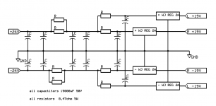
Well the pcb for capacitance multiplier is made by scafas, a member here, it's made after this schematic, i used mjl instead of tip35/3 and, because I had them readily, and they work great in the Darlington.
Toroids I have four from scrapped electronics, they are 300w each they gave 27 volt after rectifier, a bit high, but cap multiplier dropped volts to 24.
Schematics and documentation are on elliot sound webpage.
Attachments
Last edited:
This is the final, I've tried different parts, capacitors and transistors, this setup sounds the best, I've also added some heavy duty capacitance multiplier, with mjl1302a mjl3281a, the amp is dead silent, at 24 volt 1 amp bias ripple is less than 2 mv rms.
I'm gonna discard the Pcb, and make my own, but only as driver boards, output and filter go separate, with rail directly to collectors.
So now it's tedious chassis time.
It's a bit of capacitor in the power supply regardless of capacitance multiplier, it's not a trick in ripple but as the amplifier sounds, I have 15000uF x 12 and better regulators and I think I still have too few capacitors.
The PCB should be smaller with as little stripe length as possible. My output transistors have a fT of 70-80MHz at 2A and everything works fine, there are also two CCSs on the PCB. The PCB is 90 x 50mm.
Attachments
Would you recommend trying upping The capacitors? Or did I misread? Right now it's only 20000uf pr rail, class a dosent fluctuate much in current consumption as class ab.
I have seen some Nippon capacitors 35v 470000uf, also 35mm diameter, same pitch.
I have seen some Nippon capacitors 35v 470000uf, also 35mm diameter, same pitch.
I came up with the results mostly by listening to the amps, I tried a lot of power combinations and what I have now is the best I've got. At full output of 15W on both channels I have a completely flat voltage, pure DC. The current is 2A.
I've been working in A-class amplifiers since Pass released ZEN, and I've never spent on capacitors and power generally, which is much more important in A-class than in B-class amplifiers.
I've been working in A-class amplifiers since Pass released ZEN, and I've never spent on capacitors and power generally, which is much more important in A-class than in B-class amplifiers.
Attachments
Thanks for the revised schematic prasi based on John's suggestion.
John and prasi - with this new bias scheme I am interested in what type and most importantly power rating is needed to fill the position of VR3, currently shown as 470 ohms now. There are not many options available for trimpots rated over 1 watt it seems. Hopefully the power rating is lower now with the extra series / parallel resistors added.
John and prasi - with this new bias scheme I am interested in what type and most importantly power rating is needed to fill the position of VR3, currently shown as 470 ohms now. There are not many options available for trimpots rated over 1 watt it seems. Hopefully the power rating is lower now with the extra series / parallel resistors added.
Member
Joined 2009
Paid Member
the pot is shown in series with a resistor of same vale rated 1W, that would seem a good starting point.
The cheapo 10-15 turn trimpot copies (as in only US 5-6 cents each in bulk quantities) are typically what DIYs are using now and probably OK in non-critical, low current applications but this one is likely to be critical over the long term and I wouldn't use a thermoplastic moulded type like that if I could avoid it. Yes, they do melt when given enough current to deal with. Old protoypes of the multi and single-turn plastic pots were much larger, used thermoset plastic mouldings and could stand a lot of abuse, even charring - but at a price that would now scare us off.
However, if you fit smaller pot. values than fixed resistors in combination, it should be possible to cover your practical adjustment needs with a cheap, lower power rated pot. I occasionally use a big, wire-wound pot. to determine the correct total resistance value and calculate suitable trimpot + fixed resistors to trim just the essential range with either a series or parallel combination, as appropriate and according to how the ww pot. responded to adjustment during the test.
Often, you can find suitable resistors in the E12 or higher ranges that do the job without any need for adjustments, once the the approximate optimum value (if there is one) is determined. The intention in eliminating adjustments is to make a more reliable amplifier than one that remains a test-bed with an excess of adjustments, flaky components and uncertainties. These flaws remain long after you've had your fun tinkering with the amp and then become problems, when all we want is to listen to the music .
.
However, if you fit smaller pot. values than fixed resistors in combination, it should be possible to cover your practical adjustment needs with a cheap, lower power rated pot. I occasionally use a big, wire-wound pot. to determine the correct total resistance value and calculate suitable trimpot + fixed resistors to trim just the essential range with either a series or parallel combination, as appropriate and according to how the ww pot. responded to adjustment during the test.
Often, you can find suitable resistors in the E12 or higher ranges that do the job without any need for adjustments, once the the approximate optimum value (if there is one) is determined. The intention in eliminating adjustments is to make a more reliable amplifier than one that remains a test-bed with an excess of adjustments, flaky components and uncertainties. These flaws remain long after you've had your fun tinkering with the amp and then become problems, when all we want is to listen to the music
.My brother used a cheap pot to find ideal resistance values. He then used fixed resistors to set that value. I don't remember him ever finding a problem with that. My Quad 303 is the same as when set this way possibly 15 years ago. For many amplifiers they seldom were the same a year later using presets. The 303 is rather remarkable when set up correctly. Basically mid voltage point and 67 VDC plus 7 mA bias +/- 3 mA. The 303 regulates the 0V side. The 303 PSU might be adaptable to the JLH. Quad thought it worth its unusual connection.
I have often thought feeding the music into the feedback capacitor could give better sound. It's such an easy thing to try. I will draw it. With op amps this option is thought best. Given that it works the usual input could be improved. The JLH as designed would suit any preamp, this idea is low impedance.
I have often thought feeding the music into the feedback capacitor could give better sound. It's such an easy thing to try. I will draw it. With op amps this option is thought best. Given that it works the usual input could be improved. The JLH as designed would suit any preamp, this idea is low impedance.

220 ohms is typical of headphone amplifiers ( > 32 R , 220 R ideal ). Often this compromise gets better performance. It's a good excuse to use a buffer amplifier. The usual input preamp replaced with a 1 K resistor ( original input Vin side )?
That capacitor C3 not so much for quality but just ideal value can be tuned. The right low grade might be better than a high grade wrong choice. Ears are the best measuring tool for this and the value should be checked again if changing the speakers (Q of speaker mostly). 100 uf to 1000 uF perhaps.
This type of negative feedback is in many ways the better type. A very high current low distortion output is combined with the input signal nearly instantly. A 1K resistor used if you have an oscilloscope and enough voltage to drive it as in the second setion here. The exact gain of an amplifeir is it's sound more than I think is realised. If careful unity gain can be used. 2K7 would be easy to drive. A 22 uF film cap if so ( 100 V polyester ). Worth saying C1 is presented a very high quality signal. This is ideal for the bootstrap. Class AB is a larger compromise using this idea as perhaps 90% did in the 1960s.
If you used a NE5532/34 op amp and high gain transistor it can be a genuine class A design. I kept it conventional so you can have a high impedance input if you like. 3 Vrms is high for headphones. Doubless any op amp will be fine if BC337-25 or 40. A three transistor design could be better. I don't know of one I can recomend, I prefer the version shown. A NE5532 might drive 220R to 700 mVrms. A tiny bit wrong to do that. As a musical signal it might be OK. My 330R load easilly gave 3 Vrms. The graph I show is at a higher level and was for my records. The 3 Vrms would have been very good. The distortion of this design could suit the JLH. I am not a great fan of NE5532. Used with care it's a bargain and can sound fine. MC33078 is better to my ears if available. Better op amps might be on paper than in reality. Some can be a bit sureal. They seem to be video op amps made to work at 36 V.
Last edited:
As bigun suggested, I'd not use anything less than 1W.
I'd also agree with nigel that using (almost) any pot to set up and replacing it with a fixed resistor would be a good option, though having a pot does allow for replacing the transistors if you are unlucky enough to blow them - it'll remind you to check, whereas a fixed resistor might lead someone less knowledgeable about the JLH to think the circuit is fine!
If I were building it (again) I might go for a high power pot, simply because it is simpler!
I don't know if anyone has thought of using one of those 8-way DIL switches and a set of binary resistors ... but that'd be a novel solution, even if you ended up not using most of the resistors...
Curious about the idea of using binary resistors here's a follow-up:
a typical 8-DIL switch can only handle 25mA per contact. SO rather than having a complete set of 8 binary weighted resistors use 5 equal value and three binary?
Since the resistor value affects the current, the currents aren't a simple function of just the binary resistor values. Here's a simple (Fortran, sorry if you are a C fan) program to calculate the currents:
program JLH1
implicit none
real*8 :: r(8)
real*8 :: Vcch=11.4
real*8 :: RFix=47
real*8 :: I(16)
real*8 :: Rcomb, Rsave, Reff
integer*4 :: k,j,n,m
r(1)=560
r(2)=560
r(3)=560
r(4)=560
r(5)=560
r(6)=1000
r(7)=2000
r(8)=3900
do n=1,5 ! up to 5 resistors in parallel
k=1
Rcomb=R(1)
if (n>1) then
do m=1,n-1
Rcomb=1/(1/Rcomb+1/R(m))
end do
end if
Rsave=Rcomb ! save baseline resistor value
do j=0,7 ! combinations of remaining
if(btest(j,0)) then
Rcomb=1/(1/Rcomb+1/R(6))
end if
if(btest(j,1)) then
Rcomb=1/(1/Rcomb+1/R(7))
end if
if(btest(j,2)) then
Rcomb=1/(1/Rcomb+1/R(8))
end if
Reff=Rcomb+Rfix
I(k)=Vcch/Reff
k=k+1
Rcomb=Rsave ! reset for this set of calculations
end do
write(*,"('number of 560 in parallel=',i3,' currents=',16(' ',f6.2))") n,(I(m)*1e3,m=1,8)
end do
end program JLH1
Hi John,
i was wondering too that dil switch can only handle 25mA, however i could find one that can handle 150mA. 76PSB08ST Grayhill | Mouser India
Should be enough for the purpose?
regards
prasi
i was wondering too that dil switch can only handle 25mA, however i could find one that can handle 150mA. 76PSB08ST Grayhill | Mouser India
Should be enough for the purpose?
regards
prasi
- Home
- Amplifiers
- Solid State
- JLH 10 Watt class A amplifier