Member
Joined 2009
Paid Member
Hello all,
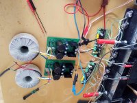
I've started on my two boards
An externally hosted image should be here but it was not working when we last tested it.
The outputs are left and right hand, the white wires
I've used Veropins for the items I will want to change
I'm making them as different boards so that I will be able to switch from one to the other to see which one I like best.
Cheers - J
Fantastic, veropins, I remember those from my young days in England.
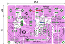
Done, as per jlh2003 schema.
'thumbs up'!
I think R16 has ended up on the wrong side of the output cap? It should be on the speaker side of the cap to allow charging/discharging of the output cap if there is no speaker connected.
'thumbs up'!
I think R16 has ended up on the wrong side of the output cap? It should be on the speaker side of the cap to allow charging/discharging of the output cap if there is no speaker connected.
Yes, corrected.
Also, I think we are done here..
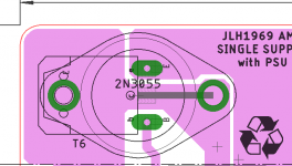
1. added option to use to-126 devices
2. added cl-60 for chassis disconnect
3. B-C-E pads for externally mounted devices.
4. pad for V+IN if someone wants to use external PSU.
5. Added special logo for "JLH 1969" , if any one has better, share the high resolution image file. I will convert it to logo and add it.
6. Recycle logo & My logo 😀
If there are no more comments, I will post files😛😛
regards
prasi
Attachments
Hello Prasi
Sorry this is a bit late, but I'm wondering about the physical dissipation in the preset pot R13. It needs to be able to handle the highest current possible, which may mean using a larger one than a 10mm(is that right?) pot.
The max. current a pot can handle is sqrt(power/R) and this should be at least equal to the max. current when set to a low or near zero value to avoid overheating the track.
If I am not mistaken (I haven't read all of the latest posts in detail) it is for a 4 ohm load, and at 24V psu the peak current out is in the region of 3A, which needs a possible base current of up to 150mA (worst case). I wonder if the resistors R1 and R2 would have to be lower?
It seems that there are not so many low gain transistors around these days but 2N3055's also suffer from quasi-saturation, meaning the gains could well be low at low voltages, unfortunately compounding the problem for 24V operation.
Sorry to be late to raise these points as you do produce good layouts!
I think it could be a good idea to have the possibility to use a RC LP-filter on the input for EMI. I was shocked when I looked at the HF on the output from my JLH placed next to my TV.. I have now added a RC by cutting traces.
Still in 2020 many supposedly A brands do not include simple RC filters at inputs of amplifiers. "Not necessary".....
the jlh thread is busy, very good.
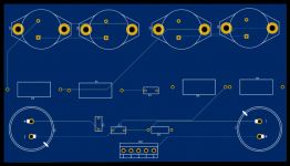
i am making a dedicated output board for jlh 2003, rails connect directly to pcb, i added 2 100nf snubbers and 2 6800uf caps, it also has the output filter, and off course the feedback.
it still needs alot of polishing, comments ideas are welcome
i am making a dedicated output board for jlh 2003, rails connect directly to pcb, i added 2 100nf snubbers and 2 6800uf caps, it also has the output filter, and off course the feedback.
it still needs alot of polishing, comments ideas are welcome
Attachments
Member
Joined 2009
Paid Member
3. B-C-E pads for externally mounted devices.
prasi
A thought: If you adjust the spacing of the BCE-pads, the PCB could cut and used with modern devices mounted directly without leads?
i see. but its first time ever used pcb software.sometimes it helps to rotate the power devices to better position the high current traces
I think you will find that HF (RFI + EMI) also enters simple audio circuits such as this JLH amplifier, via the speaker leads and direct to the circuits too. The leads are often close to TVs so they remain a problem for DIY constructors who may also use wood, composites, plastics etc for enclosures and thus have little or no shielding at all.I think it could be a good idea to have the possibility to use a RC LP-filter on the input for EMI. I was shocked when I looked at the HF on the output from my JLH placed next to my TV.....
It is still good to filter the power supply and shorten any unnecessarily long power leads from external DC supplies but better to eliminate the long leads by using shielded internal power supplies and enclosing the whole amplifier in a conventional, properly earthed metal case, if possible. Speaker leads can (and often do) have a simple RC RFI filter located at the speaker jacks.
Yes, I agree. I added RC on the output too, but still have not put a LR in series with the output. I also put ferrite cores as common mode chokes on input cables and speaker cables. In my case the amp is actually in a metal box, so it is somewhat shielded. Power supplies are outside this box (SMPS).
JLH 1996 based class A amplifier about 10 watts.
Using a +/-15VDC 20 watt SMPS to power it.
Sounds excellent through my pair of Fane 12-250TC's
I used the JLH96 as basis for this, however the first CCS variable resistor was too small and I couldnt get zero volts on output.
I increased the 220r trimmer to 1K and it works fine now.
Using a +/-15VDC 20 watt SMPS to power it.
Sounds excellent through my pair of Fane 12-250TC's
I used the JLH96 as basis for this, however the first CCS variable resistor was too small and I couldnt get zero volts on output.
I increased the 220r trimmer to 1K and it works fine now.
An externally hosted image should be here but it was not working when we last tested it.
An externally hosted image should be here but it was not working when we last tested it.
Hello Prasi
Sorry this is a bit late, but I'm wondering about the physical dissipation in the preset pot R13. It needs to be able to handle the highest current possible, which may mean using a larger one than a 10mm(is that right?) pot.
The max. current a pot can handle is sqrt(power/R) and this should be at least equal to the max. current when set to a low or near zero value to avoid overheating the track.
If I am not mistaken (I haven't read all of the latest posts in detail) it is for a 4 ohm load, and at 24V psu the peak current out is in the region of 3A, which needs a possible base current of up to 150mA (worst case). I wonder if the resistors R1 and R2 would have to be lower?
It seems that there are not so many low gain transistors around these days but 2N3055's also suffer from quasi-saturation, meaning the gains could well be low at low voltages, unfortunately compounding the problem for 24V operation.
Sorry to be late to raise these points as you do produce good layouts!
Hello John,
I dont know, if i am doing anything wrong, but pot dissipation appears to be quite low. The pot i have there is a bourns 3345p wirewound single turn 1W.
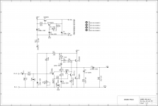
I did a sim too, could someone have a look and tell me if its correct?
interestingly, i had to lower both R1/R2 to get the bias up even for 8 ohms. and for 4 ohms, they have to be nearly halved.
As per the JLH documentation "post script" , the 2N3055 can be used provided TR3 is 2N1711. ofcourse there are MJ1500X AND MJ2119X or as per the new layout, people can even try with TO-264 type packages.
Regards
prasi
Attachments
A thought: If you adjust the spacing of the BCE-pads, the PCB could cut and used with modern devices mounted directly without leads?
1. Done!..😀

A side note: Even TO-3P devices can be mounted directly in the same pads as TO-3 and the second collector hole can be used for mounting bolt, provided , you bend the legs very close to the body. But many builders wouldnt bend it that close.
Attachments
Last edited:
Hi prasi, just a small point - in your post #6378 of the 30th April you mention you changed the pot R13 to a Bourns type 3345. The schematic shows this with a value of 2.5K. The datasheet for this pot type does not have that value (either 2K or 5K is shown).
Looking forward to your BOM, and otehr doc's, thanks.
Regards,
Gary..
Looking forward to your BOM, and otehr doc's, thanks.
Regards,
Gary..
Hi again prasi,
Looking at this pot, I can find them at Mouser - but they are listed at $20.88 USD each!! Ouch.
Do you have any other subs - does it need to be wirewound and 1 watt rated?
Could the Bourns 3362P which is cermet and 0.5W rated be OK?
Looking at this pot, I can find them at Mouser - but they are listed at $20.88 USD each!! Ouch.
Do you have any other subs - does it need to be wirewound and 1 watt rated?
Could the Bourns 3362P which is cermet and 0.5W rated be OK?
Single Turn Trimmer Resistors - Through Hole | Mouser India
Single Turn Trimmer Resistors - Through Hole | Mouser India
value is not critical as trimmer and 470 ohm resistors are in series. So even 500 ohm would be well.
what is used by builders? or no has built it yet?
Sockets to try on different resistors? then solder the final one?
Single Turn Trimmer Resistors - Through Hole | Mouser India
value is not critical as trimmer and 470 ohm resistors are in series. So even 500 ohm would be well.
what is used by builders? or no has built it yet?
Sockets to try on different resistors? then solder the final one?
Last edited:
Hello all,
I'd just finished populating these two boards when I read about 'R13' so I put my little blue trimmers on Veropins as well, thanks for that, you never know.
My next step is to check the boards with the circuit diagram and see if my Veroboard layout matches and alter that if it doesn't.
Cheers
I'd just finished populating these two boards when I read about 'R13' so I put my little blue trimmers on Veropins as well, thanks for that, you never know.
An externally hosted image should be here but it was not working when we last tested it.
My next step is to check the boards with the circuit diagram and see if my Veroboard layout matches and alter that if it doesn't.
Cheers
This is the final, I've tried different parts, capacitors and transistors, this setup sounds the best, I've also added some heavy duty capacitance multiplier, with mjl1302a mjl3281a, the amp is dead silent, at 24 volt 1 amp bias ripple is less than 2 mv rms.
I'm gonna discard the Pcb, and make my own, but only as driver boards, output and filter go separate, with rail directly to collectors.
So now it's tedious chassis time.
I'm gonna discard the Pcb, and make my own, but only as driver boards, output and filter go separate, with rail directly to collectors.
So now it's tedious chassis time.
Attachments
- Home
- Amplifiers
- Solid State
- JLH 10 Watt class A amplifier