can i replace it directly on this board without touching nothing?
Stereo JLH Hood 1969 Class A Power Amp fully loaded
will it work?
No because the package is not the same. Mj15003 has the same package and pinout than the 3055, the 2sd1047 has a TO3P package.
http://www.ebay.com/itm/HOOD-JLH-19...347531?hash=item4aeb111e4b:g:5LwAAOSw3xJVbCqr
Last edited:
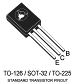
^ Typo ?.....Looked at from above and '1' is the emitter and '3' the base on most T0126 packages.
Quite right Mooly, I should have checked the source. Apologies all - the attached image here is from ST Micro who are obviously more reliable than the datasheet site on that watermark.
Attachments
Last edited:
2SD1047 is one of the best transistor for a jlh amp. In my experience, it's better than mj15003 by far
Hi Killmister, could you give some more details about this: have you done a side by side comparison and with which variant of the JLH - the '69 or whatever, and how was it different? I would be interested in knowing.
Cheers
Mike
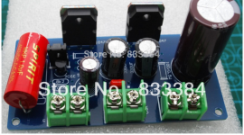
Most modern, high Ft audio transistors will also sound much better than craptanium silicon power transistors from the early years of solid state audio. The list of modern, affordable audio power transistors is long but any of On-Semi's family of 30MHz NPN transistors will work absolutely fine, as will Toshiba's 2SC5200 and Fairchilds FJA, FJL series too. Some kits only suit plastic types anyway (pic1)
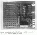
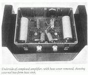
In an effort to be original though, most kits suit only T03 transistors but few if any of these transistors are now produced with high linearity and Ft chips. MJ21194 is high linearity but only 4MHz Ft and not exactly cheap. To make the most the design, you need to start with a PCB designed for plastic (TO264, TO3P, TO247) transistors, though adding short leads to heatsink mounted transistors doesn't seem to have been a problem for JLH when he developed the design (as in pics 2,3) 😉
In an effort to be original though, most kits suit only T03 transistors but few if any of these transistors are now produced with high linearity and Ft chips. MJ21194 is high linearity but only 4MHz Ft and not exactly cheap. To make the most the design, you need to start with a PCB designed for plastic (TO264, TO3P, TO247) transistors, though adding short leads to heatsink mounted transistors doesn't seem to have been a problem for JLH when he developed the design (as in pics 2,3) 😉
Attachments
Last edited:
Hi Killmister, could you give some more details about this: have you done a side by side comparison and with which variant of the JLH - the '69 or whatever, and how was it different? I would be interested in knowing.
Cheers
Mike
Hi
My comparisons are subjective. The two amps had the same coupling and psu capacitors.
The input transistor and the driver transistor were the same (2n3906 and 2sd669). The Hfe of the transistors were around 100/120 for the 3055 and 1047.
By listening, the difference is obvious and the difference in quality is much more important than with the comparison of 3055/15003 (which i've found there are close).
There is more definition, clarity, articulation and the basses are better controlled by far. I also found less problem of oscillation. (This is not due to the transistor's FT but to the wire length and metal housing of the TO3 so than the amp is prone to oscillate more easily)
The main differences in construction between the 2 amps tested are the pcb and the wire length to connect the 3055 while the 1047 are directly welded to the pcb.
Amps are 1969 model.
Watch these posts too :
http://www.diyaudio.com/forums/solid-state/3075-jlh-10-watt-class-amplifier-323.html#post4478654
http://www.diyaudio.com/forums/solid-state/3075-jlh-10-watt-class-amplifier-369.html#post5065073
Guillaume
Last edited:


Hi
Found these two amps when searched for hood 1969 pnp model.
Could some please help me out in choosing the one among them.
Hope they belong to jlh 1969 🙂
Regards
2SD669
Have you compared SD669 with 2N1711 or 2N3019 or BD139?
Yes, they both appear to be finished, commercial stereo kit pairs of the JLH'69 amp, complete with on-board, regulated power supply. They will be similar but the lower example is a PNP or reversed polarity design and uses 2 output capacitors, perhaps back to back, in an attempt make a non-polarized output capacitor or simply to make a larger capacitor. FWIW, I would choose the top example, because it has the original NPN output format and apparently uses MJ15025 transistors. Importantly, the heatsink bracket is also larger and thus more efficient at getting rid of heat. The cap quality may not be as good, but that can be changed as and when you see fit.Hope they belong to jlh 1969...
These are up-market versions of the many commercial JLH'69 kits you see everywhere on the web. However, the regulated supply amplifiers will run hot and need a lot of heatsinking so read the original design articles carefully for sizing of the power transformer and calculating suitable size heatsinks for regulated supplies - guesswork wont be good enough for longevity here.
The Class-A Amplifier Site
Last edited:
Yes, they both appear to be finished, commercial stereo kit pairs of the JLH'69 amp, complete with on-board, regulated power supply. They will be similar but the lower example uses 2 output capacitors, back to back, in an attempt make a non-polarized output capacitor. If you believe that is better then try it for yourself but whilst they may be showing pairs of good quality/brand capacitors, I don't think the arrangement will work as well as might have been imagined by the kit designer.
FWIW, I would choose the top example, because the heatsink bracket is larger and thus more efficient at getting rid of heat. The cap quality may not be as good, but that can be changed as you see fit.
These are up-market versions of the many commercial JLH'69 kits you see everywhere on the web. However, the regulated supply amplifiers will run hot and need a lot of heatsinking so read the original design articles carefully for sizing of the power transformer and calculating suitable size heatsinks for regulated supplies - guesswork wont be good enough for longevity here.
The Class-A Amplifier Site
Thanks a lot for the reply,
Am going to use

So I guess would be sufficient for this amp
Regards
Raj
Btw which caps need to be changed if I go with the first model, any sound difference with transistors used? As in the first one 15024g are used and in second mj2955 are used
The complementary MJ15024 is the regulator transistor for the PNP version and the complementary MJ2955 is the regulator for the NPN version. The power transistor roles and types in the amplifiers are thus not all the same.
If you are reading this thread, you'll see recent comments about the differences between power transistor and driver types. All components, including capacitors, have a potential to affect sound quality. However, unless you have the particular product with it's unique mix of cap. brands and grades in your hands, there is no way to predict subjective sound effects other than to say they should only be noticeable if the parts are really old or poor quality. Comments on capacitor quality apply to all audio amplifiers so you should be searching information on this formally by, for example, reading the relevant articles on the ESP website I linked for the JLH articles.
Electrolytic caps deteriorate over time. Even used well within their ratings, they are prone to faults and ageing, so reputable brand caps are essential for audio but not all are available economically in all countries. The most important caps here are the expensive power supply and output caps. Use good brands and "audio" grades there, with highest available ripple current ratings (or low ESR) for preference. Nichicon, Elna, Rubycon, Epcos etc. all make suitable grades if they physically fit the boards with their pin spacings and overall dimensions. The actual grades to compare won't be that many, since most grades are size dependent and only cover a limited range of values.
Incidentally, to begin to describe poor cap. quality: I have bought Ebay kits more than once, that even new, were already heavily pitted with corrosion under their plastic sleeving. Buyers of Nover brand caps take heed! 😡
Thanks for the inputs that helped a a lot, to be frank am newbie and don't have much knowledge on the electronics, my intention is to get this amp as a kit and place it in a cabinet and connect the transformer and play the music 😉
Don't forget to make a suitable power supply with a low-noise transformer (nobody likes a transformer that hums or buzzes under load) that supplies about 25VAC at around 4A or more. The regulators will lose about 5V if they are working properly, so the transformer AC voltage and the DC voltage after the rectifier must accommodate this. Approximately, AC(25V) » DC(35V) » DC(30V regulated).
Your heatsink example is massive and probably enough for 2 stereo pairs of amplifiers (perhaps rated at <0.2 degrees/watt?) running on a nominal 30V DC supply and 1.5A bias current. Then again, India's climate can be relatively hot for much of the year so much larger heatsinks probably are essential.
Your heatsink example is massive and probably enough for 2 stereo pairs of amplifiers (perhaps rated at <0.2 degrees/watt?) running on a nominal 30V DC supply and 1.5A bias current. Then again, India's climate can be relatively hot for much of the year so much larger heatsinks probably are essential.
Yes that's the reason i have decided to go with that heatsink of height 150mm which would be enough for handling heat, am planning to go with with 0-30, 0-30 5A rating.
Heat sinks are rated .35 degrees/watt
Heat sinks are rated .35 degrees/watt
I think your AC voltage will be excessive. 30VAC means a rectified DC of 43V and then the regulator needs to lose at least 15V for use with 8 ohm loads. This is only a nominal 10W amplifier so try to start with a modest DC supply of not much more than 27V after regulation. 35VDC before regulation is plenty for this. Otherwise, you only produce heat rather than output power.
Ohh ok then will go with 25v with 4A transformer any chance to increase the wattage from 10 to 12
The recommended power ratings, voltages and speaker impedance for the JLH'69 amplifier are tabulated in the linked article. Have you been able to read it in PDF form? If necessary, perhaps you can convert the format to a text document so that you can then use translation software.
You may notice that the amplifier is rated to use a 33VDC supply but only with a 15 ohm or higher impedance load. With 8 ohm loads, the maximum supply voltage should be reduced to 27VDC and this is why you need to be careful with the specification of that EBay kit which says the supply voltage can be 12-33V. An interesting fact about the regulator is that is not what it seems - it's really a capacitance multiplier circuit that simply cleans up noise and ripple from the rectified DC and its output voltage will simply follow the average DC input voltage, less about 15V. If this is true with the kit, it is different matter and you will indeed need a 30VAC transformer to supply this particular kit, just as recommended for the original JLH '69 design.
You could possibly increase the supply voltage by 10% to get a little more power but it t would be difficult to buy such a transformer with special voltages and hardly worth the result. Even 20% in power level (12W) would only just be noticeable. If you really needed more power than the nominal rated 10W, you would have to consider at least 15W or even doubling the power as a first step. The better solution for higher SPL from class A systems is higher speaker efficiency, where possible, as a few dB higher sensitivity is equivalent to doubling the amplifier power rating and possibly at no extra cost.
Hi,I very briefly explained what TR3 does but unless you understand how semiconductors work and are configured to to amplify signals, it probably won't mean much. Electronics is not a simple study, as I'm sure we are all aware.
BD139 is not the best transistor here but it can work OK if Hfe (gain) is high enough - like higher than median spec. value. However, the 2SD669A you were supplied with in the kit was not likely a genuine Renesas or Hitachi part anyway. You can buy bags of those copies cheaply on Ebay, Aliexpress etc. https://www.aliexpress.com/item/10P...lgo_pvid=6ec96633-245c-41f7-b746-5ff183a23ea8
I don't think you have the pinout correct when checking for an E-C short. A short should read the same in either direction. Whilst the transistor is removed, why not test other resistors in the circuit?

I finally (I think) have some time to try and troubleshoot this issue again. I measured the resistors and they all seem okay.
Another thing I saw when I removed the transistors is, that the board must have overheated like crazy. The pcb under TR1 is slightly yellowish, but under tr2 (I hope I didn't get them wrong), it is even more so.
I am replacing TR1, TR2, TR3... should I replace the TR4 also?
Regarding the BD139, I meant the bd139/16 variant, which should have a higher gain. Will it be a lot worse than the original 2sd996a? Will I be able to hear it and should replace the one the the healthy channel also?
Attachments
- Home
- Amplifiers
- Solid State
- JLH 10 Watt class A amplifier