Destroying amps...
I still haven't built a case for my amp, soooooo... I managed to short some contacts and one of the channels went out with a "thump". Both 2n3055 transistors on it went bad. The channel was "short", kicking my SMPS into error/emergency mode.
So I replaced the transistors. The music started playing beautifully again. For a few minutes, when the same kind of "thump" killed the new transistors. I thought that this time, it was my clumsy transistor mounting, and that when stuff got hot, something must have shorted somewhere.
Okay, so I bought another pair of transistors, and mounted them, this time with all the care given. The music started playing beautifully again, and the third "thump" started to frustrate me... Now I don't know enough electronics to troubleshoot the problem myself, but I think my first shorting must have killed or damaged some other components. Any idea what I should replace to get the amp alive again?
First things first. Does the other channel still work OK?
Some possibilities - the channel that blew up is oscillating, overheating the 2N3055's and then they expire. To check - do you have a meter that can measure frequency, or an oscilloscope or can you borrow one. Next time do a couple of things if you can before switching it on again. Set up a current monitor resistor (either an ammeter in series with the power supply or a low ohm resistor you can measure the voltage across). Use a current limited supply if possible, and check that the current is not excessive, or beginning to show thermal run-away.
At first sight it might be that the quiescent current is too high. The transistors will get hot and conduct more current, then get hooter because of that, then after a while blow up. Do they get hotter than they should?
Check the voltages too if you can across all the transistors. Do the base-emitter voltages measure around 0.6-0.7V? Any operating with reverse bias? Be ready to switch the amplifier off very quickly - if you have a current limited power supply or ammeter in series with the power leads you may see too high a current or the current slowly increasing. Switch off immediately!
If too high then replace the bias resistors with a higher value to bring the current to the correct level or if using pots adjust accordingly.
A quick few questions;
Was the bad amplifier working for some time before the accidental short? If so, how hot were the heatsinks? Have you checked TR3 since then too?
In agreement with others, on first power up after any work on a power amplifier, you should always use a current limiting device such as a light bulb limiter on the mains supply or large 100R resistor on the DC supply, as suggested by john_ellis. Current limiting protection has been emphasized many times already in this thread and others, with all new builds and repairs. Obviously, it applies to exposed assemblies lying on the bench too!
However, SMPSs are not good to use with a lightbulb or any type of mains supply limiter so just a resistor in series with the +supply should be an easier precaution in your situation, though it may not protect as well. A typical 100R 5W value should be OK. I have read that the bias pot. in JLH class A designs is also vulnerable and if you have bought a cheap kit, I would also check that the pot is still intact and functional. I suspect that the tiny examples I have seen in kits, are too small for reliability though to be honest, I haven't
checked many.
Last edited:
Works, if I disconnect power from the busted one. If both are connected, my smps turns on and off due to its overcurrent protection.First things first. Does the other channel still work OK?
Don't have it.Some possibilities - the channel that blew up is oscillating, overheating the 2N3055's and then they expire. To check - do you have a meter that can measure frequency, or an oscilloscope or can you borrow one.
Will try to be more cautious, yes.Next time do a couple of things if you can before switching it on again. Set up a current monitor resistor (either an ammeter in series with the power supply or a low ohm resistor you can measure the voltage across). Use a current limited supply if possible, and check that the current is not excessive, or beginning to show thermal run-away.
I didn't measure.At first sight it might be that the quiescent current is too high. The transistors will get hot and conduct more current, then get hooter because of that, then after a while blow up. Do they get hotter than they should?
There were no pots in this kit, so I guess there are bias resistors. I don't know which ones they are, though. I suppose it would be simplest if I remove the resistor and measure it?Check the voltages too if you can across all the transistors. Do the base-emitter voltages measure around 0.6-0.7V? Any operating with reverse bias? Be ready to switch the amplifier off very quickly - if you have a current limited power supply or ammeter in series with the power leads you may see too high a current or the current slowly increasing. Switch off immediately!
If too high then replace the bias resistors with a higher value to bring the current to the correct level or if using pots adjust accordingly.
Before the accidental short, the amp was working like a charm. I didn't measure the heatsink temperature, but the amp was healthy... it worked okay for months before. Didn' check TR3. Would the amp work if it was faulty?A quick few questions;
Was the bad amplifier working for some time before the accidental short? If so, how hot were the heatsinks? Have you checked TR3 since then too?
Okay, I can see why. 🙂 These resistors are becoming pretty expensive. 🙂In agreement with others, on first power up after any work on a power amplifier, you should always use a current limiting device such as a light bulb limiter on the mains supply or large 100R resistor on the DC supply, as suggested by john_ellis. Current limiting protection has been emphasized many times already in this thread and others, with all new builds and repairs. Obviously, it applies to exposed assemblies lying on the bench too!
No bias pot here. My SMPS has some form of overcurrent protection to "do hiccups" when it is loaded with 110-150% of its rated current, which is 3,2A, and both channels share it.However, SMPSs are not good to use with a lightbulb or any type of mains supply limiter so just a resistor in series with the +supply should be an easier precaution in your situation, though it may not protect as well. A typical 100R 5W value should be OK. I have read that the bias pot. in JLH class A designs is also vulnerable and if you have bought a cheap kit, I would also check that the pot is still intact and functional. I suspect that the tiny examples I have seen in kits, are too small for reliability though to be honest, I haven't
checked many.
Yes, I have confused the '69 design with the amended version of 1970 that I currently use. This adds a few other improvements as well as bias current adjustment but not all modifications may be necessary. Anyway, you don't have that problem staying with the basic design as most Ebay kits do. http://sound-au.com/tcaas/jlh1970.pdf
The SMPS hiccups aren't really protection though - more a symptom of over-stress that should be avoided. Assuming your supply is 24VDC, you need only 1.2*2 or 2.4A bias for 6-8R speakers. What is your actual supply voltage and nominal speaker impedance? You should be able to measure the voltage drop across a small value series resistor of 1R or less and then calculate the bias current current pretty easily - within the accuracy limits of the resistor and meter, at least. Cheap 5W cement block resistors are about US 50c, so they are not greatly expensive.-
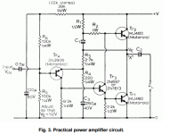
BTW, TR3 has the dual roles of splitting the signal phase between output transistors and providing them with enough drive current. If it has also failed as a consequence of trying to drive the shorted output transistors, you could still get nothing (other than the big error current at the output which promptly burns them) when you replace only them. You need to track down all failed components before powering up again and just hoping, otherwise the repair will just get very expensive.
I suggest you read the JLH articles at the Class A Amplifier Site hosted by ESP, that I linked. It might help understanding and thus suggest where and how to troubleshoot, even if the theory and advice may seem hard to follow at first.
The SMPS hiccups aren't really protection though - more a symptom of over-stress that should be avoided. Assuming your supply is 24VDC, you need only 1.2*2 or 2.4A bias for 6-8R speakers. What is your actual supply voltage and nominal speaker impedance? You should be able to measure the voltage drop across a small value series resistor of 1R or less and then calculate the bias current current pretty easily - within the accuracy limits of the resistor and meter, at least. Cheap 5W cement block resistors are about US 50c, so they are not greatly expensive.-
BTW, TR3 has the dual roles of splitting the signal phase between output transistors and providing them with enough drive current. If it has also failed as a consequence of trying to drive the shorted output transistors, you could still get nothing (other than the big error current at the output which promptly burns them) when you replace only them. You need to track down all failed components before powering up again and just hoping, otherwise the repair will just get very expensive.
I suggest you read the JLH articles at the Class A Amplifier Site hosted by ESP, that I linked. It might help understanding and thus suggest where and how to troubleshoot, even if the theory and advice may seem hard to follow at first.
Sorry for noob description. I tried measuring the resistors on both channels. The left one is healthy, right one faulty. The beige resistor on the left, good channel is 560ohm, but the right one measures only 190ohm. Could it be that measuring with other components (faulty transistor in this case) still mounted can't be done, or is it also possible that this resistor went bad when the accidental short happened?
Attachments
The 560R resistors won't be all that different when removed from the board. Carbon Film resistors like these don't drift as badly as ancient carbon composition that were common before ~1975. More to the point, you cannot measure resistance in a DC coupled circuit without it being strongly affected by parallel and series resistance of other resistors and active devices too.
If you measure same value resistors with a 3:1 difference like that, you are actually measuring something else - either because of another short or open circuit component. As it is 560R and not shown, I assume you refer to R2 shown in the attached schematic. It's not hard to imagine what might happen to a multimeter measurement if TR2 or 3 were shorted or not, so pull at least one end of reistors if you want to check properly.
If you measure same value resistors with a 3:1 difference like that, you are actually measuring something else - either because of another short or open circuit component. As it is 560R and not shown, I assume you refer to R2 shown in the attached schematic. It's not hard to imagine what might happen to a multimeter measurement if TR2 or 3 were shorted or not, so pull at least one end of reistors if you want to check properly.
Attachments
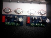
You probably know this but from your pic, I see:
1. A problem with thin aluminium being used to conduct a lot of heat. Class A, even at 10W is serious, continuous heat and unless you attach the transistors directly to large heatsinks, you will need much thicker aluminium for that bracket. Also, mount the transistors much closer to the 'sink. to reduce thermal resistance.
2. Use mounting pillars and bolts to ensure there is no chance of the board or connections shorting to the chassis and they stay in place and safe. The metal surface looks thickly coated but it only takes a little wear in one spot and a few volts to break down insulating coatings.
The 560R resistors won't be all that different when removed from the board. Carbon Film resistors like these don't drift as badly as ancient carbon composition that were common before ~1975. More to the point, you cannot measure resistance in a DC coupled circuit without it being strongly affected by parallel and series resistance of other resistors and active devices too.
If you measure same value resistors with a 3:1 difference like that, you are actually measuring something else - either because of another short or open circuit component. As it is 560R and not shown, I assume you refer to R2 shown in the attached schematic. It's not hard to imagine what might happen to a multimeter measurement if TR2 or 3 were shorted or not, so pull at least one end of reistors if you want to check properly.
So it could either be a problem with the 560R and may also not be🙂 Will pull one leg out and measure again.
You probably know this but from your pic, I see:
1. A problem with thin aluminium being used to conduct a lot of heat. Class A, even at 10W is serious, continuous heat and unless you attach the transistors directly to large heatsinks, you will need much thicker aluminium for that bracket. Also, mount the transistors much closer to the 'sink. to reduce thermal resistance.
2. Use mounting pillars and bolts to ensure there is no chance of the board or connections shorting to the chassis and they stay in place and safe. The metal surface looks thickly coated but it only takes a little wear in one spot and a few volts to break down insulating coatings.
The aluminium profile is the only one I could get in the hardware store that was big enough. There is a 150x60x25 heatsink with fans on the other side of it, not shown in the picture.
UPDATE: Removed the resistor, measured it 560R. I was quite dissapointed. Then I decided to remove TR3... and managed to damage the PCB. So I guess there will be a less difficult solution to this problem which is... to buy a new kit. :S
Last edited:
It's true that hardware stores only carry light sections of aluminium extrusions. For brackets, though, there is no point in using thin material because the transistors will run hot, even if you use large heatsink. If that is the only aluminium extrusion available, at least move the transistors closer to the heatsink. Fans, of course, will help the little heatsink, as long as they don't become audible at low audio levels.....The aluminium profile is the only one I could get in the hardware store that was big enough. There is a 150x60x25 heatsink with fans on the other side of it, not shown in the picture.
I go to building supply and metal stockists to buy off-cut material as needed. A couple of years ago, I bought 40 x 40 x 5mm aluminium in a 1m length for very little cost. Shop around, ask builders and metal fabricators for where to buy at the right price 😉
EDIT: You should be able to make a temporary repair if a track is torn or overheated. Look around for some solid wire and bridge the damage - practice your soldering skills at the same time.
Last edited:
Hello guys.
My question can be little strange because i know almost nothing about circuits...e.t.c
i want to buy this kit, which comes with Motorola 2N3055 transistor
Stereo JLH Hood 1969 Class A Power Amp fully loaded
but i read everywhere that the MJ15003 more much better.
My question is can i replace 2N3055 transistor on this kit with MJ15003 without touching ANYTHING? or it requires some circuit changes?
please help me to decide.
thanks
Though Motorola did manufacture 2N3055 by the ton, that was many years ago and then they became On-semi 17 years ago. So do you believe the marking on a brand new transistor or is it a cheap fake component? On looking at "Nuts" kit, These are a variant type 2N3055H, which is a little different and they also look like they have been used or stored for some time, so they could well be genuine and worth the extra. If you are only going to replace them, buy a cheaper kit instead.....this kit, which comes with Motorola 2N3055 transistor
Stereo JLH Hood 1969 Class A Power Amp fully loaded.....
If they are all genuine components, you can certainly just substitute MJ15003 with no other changes. It's a good plan but using genuine, recently manufactured STmicro 2N3055 transistors is also good and you may find it hard to prefer either. If you want the best, use better transistors again, like plastic types MJL21194. Genuine transistors are not as cheap as fakes or copies, of course, but that is true with most goods we buy.
Transistor types for an old design are a common DIY question which you'll find discussed many times over. Before you start the project look at some of the original considerations by reading about the amplifier on The Class A Audio Site pages hosted at the ESP website: The Class-A Amplifier Site
Last edited:
Hello guys!
Is the Tang Band W5 2143 a good loudspeaker for this amplifier?
... we accept suggestions, thank you.
Is the Tang Band W5 2143 a good loudspeaker for this amplifier?
... we accept suggestions, thank you.
The aluminium angle needs to be at least twice as thick.............. I see:
1. A problem with thin aluminium being used to conduct a lot of heat. Class A, even at 10W is serious, continuous heat and unless you attach the transistors directly to large heatsinks, you will need much thicker aluminium for that bracket. Also, mount the transistors much closer to the 'sink. to reduce thermal resistance. ..............
The long leg can be sawn to about half length and then the transistor mounted right up almost touching the other half of the angle.
But the internal face of a thick angle might not be flat.
It is better to use the outside face of the angle where you can check it is flat over the whole surface that the transistor mounts on. Or that outside face can be machined or ground to flat.
This sink is far too small.There is a 150x60x25 heatsink with fans
OK with fans for testing but not for normal listening in a quiet room.
Last edited:
Okay, so the heat management isn't perfect in my case, but the room isn't that great either. With a refrigerator and a fish tank it is far from quiet, that's why I get away with it🙂
Even though I damaged the pcb while pulling out the tr3 (2sd669a), I think I can make it work again. I tried measuring the transistor, and it conducts one way between the emitter and collector. If I understand stuff right, it shouldn't be this way.
I decided to give it one more try, this time carefully watching the temperature and measuring current through amp. I just can't get the exact same transistor where I live. Would bd139 be a suitable replacement? If not, which of the more common transistors should I get? What does TR3 "do", anyway? Is it possible it will sound different from the undamaged amp?
Last edited:
I very briefly explained what TR3 does but unless you understand how semiconductors work and are configured to to amplify signals, it probably won't mean much. Electronics is not a simple study, as I'm sure we are all aware.
BD139 is not the best transistor here but it can work OK if Hfe (gain) is high enough - like higher than median spec. value. However, the 2SD669A you were supplied with in the kit was not likely a genuine Renesas or Hitachi part anyway. You can buy bags of those copies cheaply on Ebay, Aliexpress etc. https://www.aliexpress.com/item/10P...lgo_pvid=6ec96633-245c-41f7-b746-5ff183a23ea8
I don't think you have the pinout correct when checking for an E-C short. A short should read the same in either direction. Whilst the transistor is removed, why not test other resistors in the circuit?
Last edited:
^ Typo ?
Looked at from above and '1' is the emitter and '3' the base on most T0126 packages.
Looked at from above and '1' is the emitter and '3' the base on most T0126 packages.
2SD1047 is one of the best transistor for a jlh amp. In my experience, it's better than mj15003 by far
can i replace it directly on this board without touching nothing?2SD1047 is one of the best transistor for a jlh amp. In my experience, it's better than mj15003 by far
Stereo JLH Hood 1969 Class A Power Amp fully loaded
will it work?
- Home
- Amplifiers
- Solid State
- JLH 10 Watt class A amplifier