Interesting to see the continued interest in the JLH 10W. My recommendation is to use modern high frequency output transistors. Regarding the standing current, the old type of transistors certainly had considerable gain fall-off, and in the original circuit the only place one output transistor could get current was from the other, so they both have to conduct enough current that the required peak output is available. This, it seems to me, is the main reason JLH had to use a higher current than the theoretical value. With the modern transistors the gain is far more linear to higher currents, so in principle the quiescent current might be reduced a little, but the main reason to recommend them is that the faster frequency response gives a better performance. The original circuit had a bootstrap load for the voltage amplifier stage and consequently could only rise as fast as the output transistor would let it.
I'll try and dig out the original "Letter to the Editor" (WW) from L Nelson-Jones (who raised the standing current issue) the month after JLH published the circuit and JLH's subsequent reply.....where he details his three reasons.
It was obviously in the regular the monthly edition of the mag but also in the compendium, there were two collections actually, of DIY hifi articles that WW put out in the early '70's. The latter is where I first saw it.
Down under the house somewhere.......
Cheers, Jonathan
It was obviously in the regular the monthly edition of the mag but also in the compendium, there were two collections actually, of DIY hifi articles that WW put out in the early '70's. The latter is where I first saw it.
Down under the house somewhere.......
Cheers, Jonathan
Hi Andrew, did you get a chance to follow up the Nelson-Jones article?
I'd be interested in your comments on his calculations on standing current...
Cheers,
Jonathan
I'd be interested in your comments on his calculations on standing current...
Cheers,
Jonathan
Member
Joined 2009
Paid Member
Another consideration is how the hfe of your output power transistor varies with current. In my version of this amp I chose to use parallel devices and set the current so that the dc operating point was near peak hfe and unlikely to be pushed into beta droop. Hiraga was my iniration for this consideration, he recommends setting current for the small signal transistors in one of his articles at a point where hfe varies symmetrically around the dc operating point.
Thank you Sarma I had hoped that someone would do that, good, saves me looking!
Cheers, Jonathan
Cheers, Jonathan
Last edited:
There you will get the calculations and the theoretical figure for 10 watts into 8 ohms as 875ma.
I don't know how you got that 875mA value but it's wrong.
P=I²R=V²/R=IR for constant DC
For sinewave signals the formulae need to be modified to become:
P= Iac²R= Vac²/R= IacVac for rms value of the sinewave
or
P=Ipk²R/2=Vpk²/R/2= IpkVpk/2 for peak value of the sinewave, (not peak to peak).
875mAac gives 6.125W
875mApk gives 3.0625W
An 8r0 test load needs to see 1.581Apk (=1.118Aac) for 10W
An 8ohms 2way (and multiway) speaker can draw three to five times that test resistor current on fast changing transients.
i.e. a 10W 8ohms amplifier may need to deliver upto 5Apk to properly drive a reactive 8ohms 2way speaker without current clipping.
A full range speaker without any crossover, nor any speaker zobel, may draw upto 150% of the current into a test resistor. That makes a 2.37Apk output into an 8ohms full range speaker typically clip free.
That original statement refers to output/speaker current. My reply deals only with output/speaker current and how to arrive at the current value needed for 10W into a resistive 8r0 load and what might be required for a reactive 8ohms load.Hi Andrew, did you get a chance to follow up the Nelson-Jones article?
I'd be interested in your comments on his calculations on standing current...
Cheers,
Jonathan
It has nothing to do with setting up the bias current for an output stage.
where are the articles/letters?One correspondent in the WW "Letters to the Editor" section said it did the cause of class-A a slight disservice. When calculated to supply 10 watts into 8 ohms the figure comes out at around 900milliamps. (The correspondent, Nelson-Jones, subsequently published his own similar 10 watt design in WW with a standing current of about 900mas.)
Last edited:
In summarising JLH's response, (1) does not seem to hold much validity. Music certainly has non-sinewave like characteristics, but if an amplifier can deliver a given peak power, presumably the current and voltage are the same as for a peak sinewave, so what JLH is hinting at I think is that the RMS power for music may be less than for a sinewave. (2) is quite pertinent as most loudspeakers are primarily inductors: coils of wire to drive a diaphragm through interaction with a magnetic field. Rated impedances are nominal, and very often can dip to half and increase to double, depending also whether the system is multi-unit with crossovers employing other inductors and capacitors etc. So a higher current is needed to maintain output for a lower than nominal load. (3) is probably the main issue as mentioned above: the older transistors exhibited a significant current gain fall-off with higher current. BigUn mentions operating the transistors at near peak gain: this would be an option but a secondary effect is that the capacitances (emitter-base) would increase and the driver current may need to be boosted. Modern high frequency devices tend to have a higher gain (e.g. 2N3055-20 at 4A (though running at 1 to 2A in the JLH 10W may keep the gain higher than 30) compared to an MJL3281A with gain of 75 over 1-5A range). So for the devices JLH had at the time he was in my view quite right to go for higher quiescent currents than the theoretical value.
But the newer transistors may also have a slight downside: higher quasi-saturation, with the result that the Vce may have to be kept higher, requiring a higher power supply voltage to maintain full power at low distortion. The effect of q-s is to reduce the gain at low Vce's, giving an effect similar to current gain fall off. This means that we may need not only higher quiescent current but also higher operating voltage, but a higher distortion at full output may be acceptable and is often the case for many designs.
Hi all you JLH people!
I have spent many a happy hour wading through this thread and have just built my first JLH 1969 amp from an ebay kit. I must admit to being very pleasantly surprised! I initially powered it up with a couple of 12V 2A "wall warts" and found that even at this low voltage my floorstanding TL speakers were rumbling the room. Iq was about 600mA and the heatsinks were barely getting warm. I then switched to a 24V supply (Iq about 1.5A) and my barely adequate heatsinks got quite hot to the touch without too much more noticible increase in volume. I backed off the Iq to 750mA and the HS temperature stabilised at a level where I could comfortably touch.
This got me wondering.... I know the suggested Iq is around 1.2A but how is this determined? What are the negative effects of having too low an Iq? (TR1 & TR2 are 2SD1047C's)
See my post : http://www.diyaudio.com/forums/solid-state/3075-jlh-10-watt-class-amplifier-323.html#post4478654
I have the same kit.
Transistors in mine jlh69 are 2sa970, driver is 2sc3421 and the outputs are
2sc3264 (Sanken).
The Sankens have a higher gain than the old types and give a better performance.
Voltage is ca. 30V , current 2A.
2sc3264 (Sanken).
The Sankens have a higher gain than the old types and give a better performance.
Voltage is ca. 30V , current 2A.
Nice line up. Did you need to compensate the frequency response with your Sanken output trannys?

Curious. I had to use a 33pF capacitor across the feedback resistor with MJL3281A's. Sounded very good and better than (epitaxial) 2N3055's.
Hi Andrew, the articles (JLH and the Nelson-Jones 10 watt class-A) are both on Geoff's website which I mentioned earlier #3321 and gannaji (Sarma) thoughtfully reproduced the correspondence from "The Letters to the Editor" in #3325.
Cheers, Jonathan
Cheers, Jonathan
Last edited:
JLH 2005 PSU
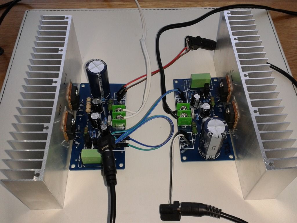
For almost a year ago I built a "2005" version of the JLH 10W Power amplifier. I never finished the complete amplifier but did some measurement using Lab Power supply.
Now I bulit a proper CAP multiplier Power supply with a voltage drop of about 3 V. The Amp is now running with +- 21 V DC.
However when I now measure the amp. I find that S/N has dropped to about 86 dB (rel. 1 W output). It was 96 dB begfore.
Two questions if someone could help here :
Has anyone here done measurements, so I know what to expect ?
What could be the problem with the new PSU ?
/Christer
Attachments
The negative clip looks like there is oscillation on the return after peak.
Does S/N ratio of 86dB mean your are measuring ~0.4mVac of hum and noise at your speaker terminals?
Whereas you had ~0.15mVac H+N before?
Does S/N ratio of 86dB mean your are measuring ~0.4mVac of hum and noise at your speaker terminals?
Whereas you had ~0.15mVac H+N before?
I looks like an oscillation, but I can only see this when the amplifier is driven to "clip". Never otherwise.
I measured with an Audio Precision P1+, and only noted the result so far. Unwtd and 22Hz-22kHz.
I will borrow an FFT to check more later this week.
/Christer
I measured with an Audio Precision P1+, and only noted the result so far. Unwtd and 22Hz-22kHz.
I will borrow an FFT to check more later this week.
/Christer
- Home
- Amplifiers
- Solid State
- JLH 10 Watt class A amplifier