I would guess that a part (maybe a large part) of that sound quality improvement comes from a lower variation in Tj as music signal varies.
Tim, do you know a retail supplier for the MJ's? They're available from RS and Farnell but they're trade only companies.
Andrew, one factor I've picked up on is the difference in the thermal resistance of the junction to case between transistors. The datasheets quote 1.5 deg C/W for the 2N3055 and 0.7 deg C/W for the MJ15003. From my heatsink calculations that will make a difference of 10 deg C at the junction even with my low voltage version of the amp.
Regards Ned
FYI RS, Farnell and CPC will accept orders on line from anyone.
I didn't realise that about RS. Useful to know. Farnell need a minimum order of £20.
Hi
Just seen this thread. Built a a pair of these JLH amps for a friend some years
ago. I used Sanken 2SC2922s for the o/p devices as they did not suffer from
beta droop. Dont know if you can still get these.
Other than the o/p devices the rest of the circuit was as JLH designed it and didnt oscillate or do anything funny. Power supply used gyrator like regulators. Sounded very nice at the time.
Hi
Just seen this thread. Built a a pair of these JLH amps for a friend some years
ago. I used Sanken 2SC2922s for the o/p devices as they did not suffer from
beta droop. Dont know if you can still get these.
Other than the o/p devices the rest of the circuit was as JLH designed it and didnt oscillate or do anything funny. Power supply used gyrator like regulators. Sounded very nice at the time.
Those 2SC2922's look like very nice devices. They are "quicker" devices and the Cob = 250pF, 4 times less than MJ15003. I would have been concerned about oscillation but you say they were fine. I'm sure they will show a much better slew rate than the MJ's on a square wave input. Don't know if one would hear an improvement but it could as the Toshiba I used on the input made a difference with the "attack" of a note. Pianno and strings are just super. So maybe the Sankens can do the same.
2SC5200 Cob is a mere 200pF. Cheap and easy to find...
TRANS NPN 250V 17A TO264 2SC5200/FJL4315 Fairchild Semiconductor Datasheet
TRANS NPN 250V 17A TO3P 2SC5242/FJL4313 Fairchild Semiconductor Datasheet
TRANS NPN 250V 17A TO220AB FJP5200 Fairchild Semiconductor Datasheet
TRANS NPN 250V 17A TO264 2SC5200/FJL4315 Fairchild Semiconductor Datasheet
TRANS NPN 250V 17A TO3P 2SC5242/FJL4313 Fairchild Semiconductor Datasheet
TRANS NPN 250V 17A TO220AB FJP5200 Fairchild Semiconductor Datasheet
Last edited:
There's a lower gain (Beta 55 min) part marked with an "R"
There's a higher gain (Beta 80 min) part marked with an "O"
Lower gain choice might be closer to a drop-in for 2n3055?
I would still plan ahead for reducing the drive current.
Higher gain and less droop isn't going to need so much...
If you adjust bias, then no harm in the higher gain part...
There's a higher gain (Beta 80 min) part marked with an "O"
Lower gain choice might be closer to a drop-in for 2n3055?
I would still plan ahead for reducing the drive current.
Higher gain and less droop isn't going to need so much...
If you adjust bias, then no harm in the higher gain part...
Last edited:
Tim,
Thanks for the link to CPC, tried a search for MJ15003 on the net but CPC didn't come up. There's a price break on 10+ so since I need 8 for four channels, it was cheaper to order 10, which I did this morning.😀
I'll have a few listening sessions before I change the transistors, I just hope my cloth ears can tell the difference.
Regards
Ned
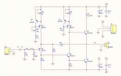
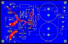
my jlh-2005
Repost it here by Johnathan's suggestion...
Just finish my first JLH-2005. The circuit is from this link:
The Class-A Amplifier Site - JLH Class-A Update
schematic and pcb attached.
A few thought about the design
1. The original 1969 design use 2N3055 as Q1 and Q2. Then changed to MJ15003. I'm thinking of some other subsititutes such as 2N3773, MJ21194 or 2SC5200
2. Can I use 2SA1358 as replacement of BD140? it's complementary of 2SC3421.
3. How to set the value of VR1, VR2 and VR3? in other words, what current should those 3 current sources be?
4. Is the large polygon pour on PCB good for audio amplifier?
Attachments
Tim,
Thanks for the link to CPC, tried a search for MJ15003 on the net but CPC didn't come up. There's a price break on 10+ so since I need 8 for four channels, it was cheaper to order 10, which I did this morning.😀
I'll have a few listening sessions before I change the transistors, I just hope my cloth ears can tell the difference.
Regards
Ned
You should order more than you need and measure the hfe on each. These parts MJ15003 I found had huge variants on hfe. I also ordered 10 of which 2 were not usable at all as the hfe readings were below the specified value. I was quite disappointed with tolerance actually.
Repost it here by Johnathan's suggestion...
2. Can I use 2SA1358 as replacement of BD140? it's complementary of 2SC3421.
Yes you can, but no sonic improvement has been reported with that part. In other words, it will not matter which part you use there.
I think I'll have to set up a test circuit to verify the dc gains of each of the transistors. The first thing however will be to check the markings on the transisitor case to see if they correspond with the manufacturers data. I've hear that the MJ15003 is one of the most faked transistors.
Assuming everything is ok with the transistors I'll select the best matches for each output stage.
Cheers
Ned
Assuming everything is ok with the transistors I'll select the best matches for each output stage.
Cheers
Ned
Sil,
I suggest you add a series resistor to each of the current setting Vr1 Vr2.
Try 100r for Vr1 and 10r for Vr2.
This allows you to check and set the target currents for these two stages.
Initially you set the Vr to maximum resistance. This passes minimum current through each stage and that way you don't blow up the amplifier at first power up.
Start with Vr3 set to maximum. This will leave Q5 becoming current starved as you increase IcQ4. The current through R11 must be >>IcQ4/100 and could rise as high as IcQ4/2
Hi Andrew,
Thanks for the suggestion. If I use 100r for Vr2, in series with a 1.9k, does it have enough range for adjustment? the same with vr2
Thanks for the suggestion. If I use 100r for Vr2, in series with a 1.9k, does it have enough range for adjustment? the same with vr2
it's better to order pair matched parts. hfe doens't mean all. The curves should be matched.
As for power transistors: Beta droop at ~1.5x quiescent
current should be matched. If they don't match at lower
current, its no big deal, the global loop and offset CCS
can handle it. But if droops are wildy different, you are
screwed! At that point you might look to SRJLH if you
still determined to make use of mismatched devices...
The npn driver and pnp error detector are doing completely
different things. Not optimal that they should compliment.
PNP should be optimally sized for gain at only a few mA.
And the NPN driver sized for best gain at around 250mA.
Keep the Vr values the same.
2k +100r gives a range of 100r to 2100r, i.e. a current range of 0.3mA to 6mA
50r +10r gives a current range of 10mA to 60mA
2k +100r gives a range of 100r to 2100r, i.e. a current range of 0.3mA to 6mA
50r +10r gives a current range of 10mA to 60mA
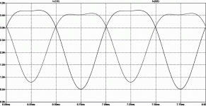
Here's a plot of currents showing some serious droop
The peak current is "supposed" to be 2x the quiescent
but we can see it never gets there!
Illustrating why matching of this flaw is important.
Its not hard to set up a quick test...
The peak current is "supposed" to be 2x the quiescent
but we can see it never gets there!
Illustrating why matching of this flaw is important.
Its not hard to set up a quick test...
Attachments

- Home
- Amplifiers
- Solid State
- JLH 10 Watt class A amplifier