I don't have Traxmaker, so the file won't help at the moment. I was thinking of the graphic so that I could use the iron-on PCB technique. Is it possible with Traxmaker to have an image like you posted, except without the silkscreen overlay? I'm not in a rush so if you are planning revisions I can wait.
I will check your layout against the schematic, I'll try to get to it within the next day or two or three. I'm not much of a PCB designer either, only done a few, but I'll check it out. 😀
I will check your layout against the schematic, I'll try to get to it within the next day or two or three. I'm not much of a PCB designer either, only done a few, but I'll check it out. 😀
Nice layout. You've got some experience here, obviously. Any chance of you posting just the pattern, like LaZarus did?
LaZ, old buddy, I haven't deserted you. I'll still check your layout.
LaZ, old buddy, I haven't deserted you. I'll still check your layout.
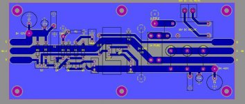
LaZarus, I checked out your layout. There's one problem, the output stage isn't correct. You haven't got a connection for Q2-C, but instead have R10 running directly to Q2-E/Q1-C.
I'd also consider moving Q8 closer to Q7 and, in general, make the traces to all the transistors smaller, it will be hard not to make a solder bridge with the traces so big connecting to the close spacing of the transistors.
Hope this helps.
Paul
I'd also consider moving Q8 closer to Q7 and, in general, make the traces to all the transistors smaller, it will be hard not to make a solder bridge with the traces so big connecting to the close spacing of the transistors.
Hope this helps.
Paul
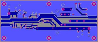
Yes, just the pattern of the copper so I can use it to make my own PCB from your artwork. I can print it on to transfer paper, then iron it on to a copper clad board.
If you wish to share. If not, that's okay.
If you wish to share. If not, that's okay.
😱 Oops, a major error in my layout. I have corrected it, but I must admit that the PCB of Calebay looks better.
Great, I will email you.
I don't know if I'm qualified to comment on whether your layout will hum or not, but I'll give it a look over.
I don't know if I'm qualified to comment on whether your layout will hum or not, but I'll give it a look over.
hello
i have a question.
what do i adjust whit VR1, VR2 and VR3. in the updated 15 watt version?
i have a question.
what do i adjust whit VR1, VR2 and VR3. in the updated 15 watt version?
Hello agin
I have made a little test setup whit 1 channel jlh 15w updated. but it seems i have a problem whit the DC-ofset. when nothing i connected to the input i have about 700Mv!! on the output over a 10R resister. but i then put my fingers on the shield of the input phone jack the DC-Ofset reduces to 48Mv. what have i done wrong?
Mvh. Carsten.A
Carsten
VR1 sets the output dc offset and VR2 the output stage quiescent current. These controls interact to a certain extent so adjustment must be iterative. The method of setting VR3 is described on the webpage from which you obtained the schematic:
http://www.tcaas.btinternet.co.uk/jlhupdate.htm
With regard to your output offset variations, it sounds like you have instability in the dc offset ccs as described in the 17/08/2003 addendum on the above webpage.
Geoff
thx geoff
now i tryed changing the input cable. and now the DC-ofset is stable, and i can adjust it to zero. but then when i try to connect my preamp, using 3 470nf in paralel, the DC will rise to 500mv.
do you think its still that 17/08/2003 addendum thing, thats causing that. or it might be something else?
now i tryed changing the input cable. and now the DC-ofset is stable, and i can adjust it to zero. but then when i try to connect my preamp, using 3 470nf in paralel, the DC will rise to 500mv.
do you think its still that 17/08/2003 addendum thing, thats causing that. or it might be something else?
Carsten
I assume the 3x470nF you refer to are for C1. The output offset etc should be adjusted with the amp warm and the input side of C1 shorted to earth.
If the offset then changes when the short to earth is removed and a source is connected, the most likely cause is that outlined in the 17/08/2003 addendum, assuming that you have omitted the capacitor (C4) in the feedback network. An alternative possibility would be an error in the ground wiring/connections, but I feel that this is less likely.
The ccs instability readily manifests itself by a fluctuation in output dc offset when a hand is moved near to Q5/Q6 or when the circuit around these transistors is probed for voltage measurements.
Geoff
ok
ill now tryed to short the input to input GND, after that amp is warmed up. and the DC stays at zero. no matter if its shorted or not.
then i connected the preamp agin, and the DC goes to 500mv. but its not when the shield touch, its when the signal touch the pre out. so does than mean something is wrong the the 3 470nf i use for C1 since they do not block out the dc for the pre out?
Well, it's possible but it is easy to check with your multimeter to see if you have a dc path through C1.
nope i was wrong it is when the shield touch the preamp phono jack, that it goes to 5-600mv
realy don't get it.
realy don't get it.
Hello
after some more testing i now found out that the amp is very unstable when its cold, when its cold i can change the DC-ofset from 1,2v to 20mv, and i can change the Iq by 0,2 amp. justy by moving my hand near the indput cable.
so from what i can read from your site, i have to change the 2sa970 to some slower tranis.
do you think that also will cure the problem i get when connecting it to a pre amp? or do i need to do more
Mvh. Carsten.A
- Home
- Amplifiers
- Solid State
- JLH 10 Watt class A amplifier