no body reply?
I test it last night,Rf is 1.8Kohm at first,I think it's the post#1261 shape,but from my speaker is so loundness of treble,I feel so surprise...so I change Rf's value to 9Kohm,yes,now I heard the bass,and treble is sounds comfortable...and I try 22Kohm,but the bass is enough,but the treble is weak...ah,now I know the feed back loop can effect the output character in this amp...
and I suggest Rf is from 4.7Kohm to 10Kohm...
C2 is 10uF MKP capacitor,you can try it's value from 2.2uF to 10uF,match with Rf,I think it has the best result you wanted.
enjoy!
WINCO
Re: no body reply?
Winco:
your circuitry isn't exactly JLH. It is essentially a normal voltage amplifier + JLH's phase-splitter + output stage. That's fine in and by itself. If you want, you can use P-channel jfet and flip its position.
Winco:
your circuitry isn't exactly JLH. It is essentially a normal voltage amplifier + JLH's phase-splitter + output stage. That's fine in and by itself. If you want, you can use P-channel jfet and flip its position.
Re: Re: no body reply?
yes,tlf9999:
you are a good guys!
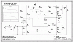
I modified X-PRO's JLH mos version,the bass comes out,but there occur something unexpected...
first is the singer's dentilingual are more clearly,somthing likes have been delayed...
second is when I turn volume knob,in it's nearly max power,the amp cames unstable.(I think this is the 2N5551 bias is not good)
I don't know what to do now!?
in fact,Post #1213 schematic is works well,only short of some bass...
puzzle!
regards
WINCO
😕
tlf9999 said:Winco:
your circuitry isn't exactly JLH. It is essentially a normal voltage amplifier + JLH's phase-splitter + output stage. That's fine in and by itself. If you want, you can use P-channel jfet and flip its position.
yes,tlf9999:
you are a good guys!
I modified X-PRO's JLH mos version,the bass comes out,but there occur something unexpected...
first is the singer's dentilingual are more clearly,somthing likes have been delayed...
second is when I turn volume knob,in it's nearly max power,the amp cames unstable.(I think this is the 2N5551 bias is not good)
I don't know what to do now!?
in fact,Post #1213 schematic is works well,only short of some bass...
puzzle!
regards
WINCO
😕
Winco:
nice to see that you are successful finally. Good job.
However, I never understood why you decided to go such a non-JHL route, when so many other JLH variations have been successfully built. I am just not sure what advantages your implementation has over others.
nice to see that you are successful finally. Good job.
However, I never understood why you decided to go such a non-JHL route, when so many other JLH variations have been successfully built. I am just not sure what advantages your implementation has over others.
tlf9999 said:Winco:
nice to see that you are successful finally. Good job.
However, I never understood why you decided to go such a non-JHL route, when so many other JLH variations have been successfully built. I am just not sure what advantages your implementation has over others.
thank you,my friend:
I have settle the short of bass problem of JLH1969 by no using a big ouput capacitor,and the treble and mediant still very good...
I suppose JLH1969 can't process bass well,all because it's pre-stage,the negative feed back style is out of the times...
second is the JLH mos version is class-ab,more green...
now I success(just a little),but I will keep trying...
😉
enjoy!
WINCO
Find the lost strong bass...
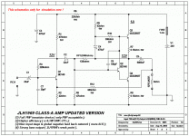
this is my new design,using PNP transistor device,I do many simulation with it,final I got this schematics:
but I really don't know why it can output 6.5W(RMS) with 1A biasing(normally it need about 1.3A biasing here)?
And I replace all PNP with NPN,but it's THD increase...
If somebody use software to simulation,please do it in your PC,
and tell me what you got,thank you!
😎
Attachments
Hi Darkhorse,
Sorry to be the bringer of bad news, but there are problems here; the most significant being two series 'C's within the global NFB loop - C2 and C5.
You will end up with bass driver cone breathing in sympathy with subsonic input and with music driven output stage bias voltage (12V)variation.
Some CDs carry sub 10Hz conversion error waveforms, and these could end up being amplified more than the music, the result being considerable bass cone drive that could distort the desired audio signal.
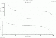
For an amplifier to operate correctly at AF it should not have a rising amplitude response below 10Hz due to phase change within the NFB loop. ( You have not fully shown this on your amplitude plot ! )
If you use ported or large bass driver types the momentary music induced voltage offsets will be clearly visible as cone movement, and possibly audible as a 'puff' sounding air motion imbalance upon bass reproduction. My simulator shows this output offset increasing as the input frequency is decreased below 200Hz. Also don't forget to simulate with a virtual loudspeaker because the distortion can become much greater than expected at some frequencies.
Cheers ........ Graham.
Graham Maynard said:Some CDs carry sub 10Hz conversion error waveforms, and these could end up being amplified more than the music, .
Graham, look at the scale used on the graph.
Darkhorse, if your bias is 1amp, at most the amp can output 1amp. so for an 8-ohm load, that's about 4wrms. I would say you are likely in the 2wrms range in terms of output.
tlf9999 said:Darkhorse, if your bias is 1amp, at most the amp can output 1amp. so for an 8-ohm load, that's about 4wrms. I would say you are likely in the 2wrms range in terms of output.
This is the case with true SE amp but the JLH is not pure SE.
With the effect of current sharing on the o/p transistors and the bootstrap on the output 1 amp bias can = about 2 amps output
So the o/p is push pull controlled with one transistor - neat & nice sounding....😉
Hi tlf9999,
But I already had, so what is your point ?
Have you actually built SS amps with 2xC in the NFB loop ?
I have, and I am writing from experience !!!
Cheers ........ Graham.
But I already had, so what is your point ?
Have you actually built SS amps with 2xC in the NFB loop ?
I have, and I am writing from experience !!!
Cheers ........ Graham.
Graham, my point is for you to read the scale of the graphs. If you still cannot get it, let me know and I am happy to elaborate.
Sometimes, not having a bad experience is in itself a good experience.
Sometimes, not having a bad experience is in itself a good experience.
hi,friends...
but not all,and I think JLH isn't not pure SE nother pure PP...
it's efficiency about 30%,I do simulation with PNP version,with 28V power supply,and 1.1A biasing,easy up to 10W(RMS)...that is to say it's most output 1.775A,if it is PP,it only need 0.89A biasing...
😉
yes!I am agree with Mr.mike...mikelm said:
This is the case with true SE amp but the JLH is not pure SE.
With the effect of current sharing on the o/p transistors and the bootstrap on the output 1 amp bias can = about 2 amps output
So the o/p is push pull controlled with one transistor - neat & nice sounding....😉
but not all,and I think JLH isn't not pure SE nother pure PP...
it's efficiency about 30%,I do simulation with PNP version,with 28V power supply,and 1.1A biasing,easy up to 10W(RMS)...that is to say it's most output 1.775A,if it is PP,it only need 0.89A biasing...
😉
How about Single Ended Push Pull?
Voltage control upper device for entire cycle, current control on negative half cycle is lower device.
Cheers,
Hugh
Voltage control upper device for entire cycle, current control on negative half cycle is lower device.
Cheers,
Hugh
...
😀
Cheers again
yes,I think so too=SEPP!AKSA said:How about Single Ended Push Pull?
Voltage control upper device for entire cycle, current control on negative half cycle is lower device.
Cheers,
Hugh
😀
Cheers again
Hi tlf9999,
I told you - I had already read the graph.
Is there something about this that you cannot understand ????
What has the scale used by Darkhorse got to do with anything relating to this circuit's response below the 20Hz I was posting about ????
Please see what Darkhorse has not posted (investigated?) about the behaviour of this circuit when the drive is sine and the load a perfect resistor.
This illustrates inadequate sub-sonic circuit stability for use with full bandwidth CD/SACD/DVD-A audio output, genuinely full range real-world loudspeakers, and typical PSUs.
Isn't it pathetic how every time I try to make a mannerly contribution there is always some smart Alec who pops up with irrelevent argument and childish personal commentary.
I was not wanting to cause embarrassment to Darkhorse, but then you *tlf 9999* started up as if I was some thicko who could not read, and thus you have ended up making a challenge about something which you say you have no experience of !!!!
Or was there something else that was going to make you happy via its elaboration ?
I have attached the forward amplitude/phase characteristics when the source has 1000 ohms serise resistance.
Cheers ......... Graham.
Attachments
...
hi,Mr.Graham:
yes,I forgot to simulating in very low frequency(lower than 20Hz),sorry!I will do it tonight and show you the graph...
but I don't think CD can process so low frequency!?
can you do me a favour to adjusting the cared value to even the curve?thank you!
I think this modification is not only by me,but also you all,facing the JLH1969 original version has not good bass,you and I who have interesting in JLH should do something to update it!am I right?
cheers...
WINCO
😉
Graham Maynard said:Hi tlf9999,
I told you - I had already read the graph.
one can read a graph and that alone doesn't assure his thorough understanding of it.
and if you don't mind, let us know which CD player / CDs can output sound in the 0-2hz range, please.
I sense frustration here:
I told you - I had already read the graph.
Is there something about this that you cannot understand ????
The peak is just below 2 Hz, not 20 Hz. Which is a less oblique way of saying what I guess this guy was trying to say:
one can read a graph and that alone doesn't assure his thorough understanding of it.
and if you don't mind, let us know which CD player / CDs can output sound in the 0-2hz range, please.
- Home
- Amplifiers
- Solid State
- JLH 10 Watt class A amplifier


