millwood said:just a word of caution for those of you wanting to do cap-less with the mosfet: the DC voltage does drift more than on the bjt version. over a long period of time (5 - 8 hours), mine drifts about 100mv, vs. about 10mv on the bjt version.
No o/p cap and no feedback cap will be give significant better sound.
if you look around at geoff's site...
www.tcaas.btinternet.co.uk/
...there is an elegant description of how to significantly reduce the dc offset problem. Needs some attention to set up but essentially solves the problem.
I think it will be OK for the MF version but i'm not 100% sure.
mike
Hi Dragance007,
Your MOSFET versions looks very nice indeed, neat and sharp 😎 , with a cute little heatsink to boot.. yehh that one looks a liiiiiiiiiiiiiiiiiiiiiiiiiiiiiitle bit too small 😉 .. Millwoods solutions was to use a PII (?) heatsink and I think that's cool too 😎 .. it sells for about 15 Euro a piece around here...
It's real good to hear you had a nice time with it... I hope you get it going soon again and comment a bit more your perceived performance of the amp ..
Best regards,
Thijs
PS
Did you use a compensation cap?, value?, MOSFET gate snoopers values?, equal drivers-resistor, values? 😉
Re: assembly question
Hi Luke
It's nice to see you use my work.🙂
the turn-on/off thumb is present in my amps. Turn on: It's a bit louder than in my 1996 project. My digital V meter reads somewhat near 1V and settles quickly to the normal dc-offset value.
Turn off is not aubile only visible in the movement of the driver unit.
I've decided to leave it this way for my amp anyway. Any future amps might have a relay and series-resistor circuit in which the relay at rest would short the speaker, and engaged would short the series resistor.
IMHO the louder thumb is related to the introduction of the ccs circuit for the first stage replacing the 7815.
I think the 7815 behaviour on a rising input is more gentle than the behaviour the ccs circuit.
and thus the thumb is more audible with the 2003 circuit
Dutch
Luke said:Hi All,
im still building the chassis and making Dutch DIYs boards. Thanks Dutch🙂
But I have read somewher in this huge thread that turn on/off thump may be present in this amp.
Would the following elektor circuit solve the turn on thump?
http://mitglied.lycos.de/Promitheus/delay_circuit_for_toroids.htm
If it does I cant see how it would fix turn off thump, is there any simple way to cure this?
any help appreciated🙂
Hi Luke
It's nice to see you use my work.🙂
the turn-on/off thumb is present in my amps. Turn on: It's a bit louder than in my 1996 project. My digital V meter reads somewhat near 1V and settles quickly to the normal dc-offset value.
Turn off is not aubile only visible in the movement of the driver unit.
I've decided to leave it this way for my amp anyway. Any future amps might have a relay and series-resistor circuit in which the relay at rest would short the speaker, and engaged would short the series resistor.
IMHO the louder thumb is related to the introduction of the ccs circuit for the first stage replacing the 7815.
I think the 7815 behaviour on a rising input is more gentle than the behaviour the ccs circuit.
and thus the thumb is more audible with the 2003 circuit
Dutch
Hi tscharma. I did not change anything in your circuit. I seems to work just fine 🙂 Maybe will play a litle bit when i repair it and get a biger heatsinks.
It is nice idea to use a processor heatsink/cooler for amp, but i pesonally dont like to mix the music with a fan noise
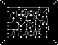
I attached the small JPG of mine PCB. I belive it is good size.
It is nice idea to use a processor heatsink/cooler for amp, but i pesonally dont like to mix the music with a fan noise
I attached the small JPG of mine PCB. I belive it is good size.
Attachments
Hi Dutch,
thanks for making your pcb available🙂 I will see how I go with turn on/off thump, perhaps your relay at speaker output is better than slow turn on circuit asfar as protecting drivers. I think this voltage would not be good for drivers after long periods of time.
thanks Arthur
thanks for making your pcb available🙂 I will see how I go with turn on/off thump, perhaps your relay at speaker output is better than slow turn on circuit asfar as protecting drivers. I think this voltage would not be good for drivers after long periods of time.
thanks Arthur
JLH MOSFET preamp?
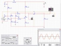
I was tired of hooking up my php850 as a preamp for testing purposes. so I built a repamp, based on the JLH breadboard I used a while ago to test my JLH1969 BJT version.
Here it is.
some performance number (per simulation, 🙂):
THD: 0.005% - 0.006% from 1khz to 20khz.
frequency response: flat all the way to 10mhz (didn't try beyond that). phase margin at 10mhz is -42 degrees.
the output stage runs very hot, at about 40ma, and R14 dissipates about 0.6w (use 1w power resistor). 470ohm is about the upper limit for R14. You can still run it a little biit hotter - I used a 100ohm 5w resistor for R14 (180ma idle current). Q2 needs a heatsink if you intend to run it this hot. This preamp is also quite stable thermally.
you can replace R14 with a CCS which will turn it essentially into Rod's preamp.
the amp has a gain of 2x, and can drive load as low as 56ohm (for 47ohm load, thd worsens to 0.011%@20khz - not bad). so it can be used as a headphone amp if your headphone has sufficient impedance.
Q2 can also be a medium power BJT but that does not deliver as good a performance as the mosfet. If your anticipated load is high (like 10K or above), you don't need to drive the output stage this hot. R14 can be then set higher, like 1k but too big as it may sufficate current for the input stage and the mosfet.
Attachments
Maybe this is not the place for this question but, milwood what softweare do you use for your simulations? Where can i get it? Is it expensive ?
Tube_Dude said:Do this experience...disconnect the output cap...and without a load see if the inrush current are gone!!
I bet ...Yes!!😉
from my earlier post:
the inrush current is large indepdent of: size of the cap (470uf vs. 3300uf I have tried), with or without a load attached, single rail vs. dual rail operation (thus no cap at all).
to make sure that my memory wasn't faulty, I doublt-checked it today: the idle current is the same, with or without the load attached. thus, the output cap isn't the problem.
Anyway, I couldn't figure out what the cause is for the in-rush current. I suspect the the decoupling cap on the input stage is the root cause.
Dragance007 said:Maybe this is not the place for this question but, milwood what softweare do you use for your simulations? Where can i get it? Is it expensive ?
it is an old student version of multisim (from four or five years ago).
I also use Protel DXP demo, available from protel.com. It is good for 30 days. After that, you have to either buy it (expensive) or reinstall the whole thing (in my case, formatting the harddrive, reinstall windows and the protel dxp). Protel is more elaborate but has a steeper learning curve. multisim is more user-friendly.
Multisim also has a demo for download. I think it is now part of circuitmaker (I haven't tried it).
edit: protel dxp does PCB but I haven't fully figure out how to use it yet.
edit 2: you can also download ltspice from linear.com. It doesn't have as much real life devices but can be very helpful in validate a design / concept.
millwood said:I suspect the the decoupling cap on the input stage is the root cause.
the inrush current appears to be small at turn-on, and then quickly reach its peak (within the first couple seconds) and declines gradually from there. the whole process takes about 20-30 seconds at the outset to stabalize. It is longer for the lower output device than it is for the upper output device.
the center voltage (where the feedback picks up) starts at a couple volts and then gradually reaches about 50% of the rail.
that is consistent with the volt transients on the base of the input transistor: at turn on, the decoupling cap (470uf in my schematic) is being charged up by the decoupling resistor (10k) from the rail, it clamps down the base voltage on the input transistor, thus the voltage on the output cap, causing a large Vgs on the upper output device. as the decoupling cap is charged up, the base voltage appearchs 50% of rail, reducing the Vgs on the output.
one solution may be to use an inrush limiter on the lower output device or on the rail. not sure what it will do to the sonics.
millwood said:
to make sure that my memory wasn't faulty, I doublt-checked it today: the idle current is the same, with or without the load attached. thus, the output cap isn't the problem.
Of course the idle current is the same with or without the cap and load attached...where the cap is inportant is a the turn on as the cap must be DC charged to half the suplly voltage...and a big capacitor will need a high turn on charging current.
Tube_Dude said:
Of course the idle current is the same with or without the cap and load attached...where the cap is inportant is a the turn on as the cap must be DC charged to half the suplly voltage...and a big capacitor will need a high turn on charging current.
without a load attached, there would be nothing to charge: there is no loop involving the output cap. it might as well be taken out of the whole circuitry.
and the inrush current problem still exists with the cap being taken out. so the output cap cannot be the cause of the inrush current.
edit: i misspoke earlier. the "idle current" I was referreing to is the measured voltage transient on the two source resistors. At idle, they are tied to the idle current. during turn-on, they are tied to the inrush current. Should have been more careful, 🙂
millwood said:that is consistent with the volt transients on the base of the input transistor: at turn on, the decoupling cap (470uf in my schematic) is being charged up by the decoupling resistor (10k) from the rail, it clamps down the base voltage on the input transistor, thus the voltage on the output cap, causing a large Vgs on the upper output device. as the decoupling cap is charged up, the base voltage appearchs 50% of rail, reducing the Vgs on the output.
this is also consistent with the timing difference between the upper and lower transient current: the current peaks later for the lower output transistor and the whole process takes longer: because the lower output device has to wait for the voltage on the collector resistor on the input transistor to build up.
Once that happens, the lower output transistor begins to turn on, in effect, draining current from the upper output transistor and delay the build-up on the center voltage.
so if we can prevent the lower output transistor from turning on so soon, we can speed up the transient process and potentially reduce the inrush current.
So....You must check the others time constants in the amp.
Playing with the values of the input capacitor and not forgeting the bootstrap capacitor.
Playing with the values of the input capacitor and not forgeting the bootstrap capacitor.
Tube_Dude said:So....You must check the others time constants in the amp.
no kidding, 🙂
yes, it is the input decoupling cap (470u in my schematic). together with the 10k decoupling resistor, the time constant of this r/c network is about 4.7s. at abot 5x time constant (23 seconds), the network is about fully charged up. That is about how much time it takes for the bias current to stablize in my jlh as well.
unfortunately, I don't have a smaller cap so I parallel'd a 1.5k trimmer to the 10k resistor and my bias current stablized now in a couple seconds.
so the way to go is to use a 47uf cap to decouple the front end, rather than the 470uf cap. I originally had.
unfortunately, I don't have a smaller cap so I parallel'd a 1.5k trimmer to the 10k resistor and my bias current stablized now in a couple seconds.
so the way to go is to use a 47uf cap to decouple the front end, rather than the 470uf cap. I originally had.
Why not just remove the capacitor completely? You seem to be quite happy connecting the input and feedback nodes directly to the supply rail. Try a simulation, it will work.
millwood said:I thought about this more last night and here is the shocker: the 1969 can work under dual rails with zero modification. The two "grounding points" are 1) the decoupling cap on the input stage, and 2) the dc blocking cap on the feedback loop. However, the supply rails are just like ground to A/C signals. so for DC blocking purposes, it doesn't really matter where you tie them (well, unless they are incorrectly polarized). So you can either tie them "properly" to the ground, or to the negative supply rail.
simulated it this morning: it worked;
breadboarded it this morning: it worked.
Geoff said:Why not just remove the capacitor completely? You seem to be quite happy connecting the input and feedback nodes directly to the supply rail. Try a simulation, it will work.
Excellent reading comprehension on your part, Geoff! I was thinking actually to forgo the whole amp and directly hook the speaker right into the mains.
Will you put a plug for me on your website?
🙂
Re: JLH MOSFET preamp?
I actually hooked up a speaker to it directly and it did make sound, at low levels, tho.
so if you desire, this can be made into a two-transistor SE amp.
millwood said:the amp has a gain of 2x, and can drive load as low as 56ohm (for 47ohm load, thd worsens to 0.011%@20khz - not bad). so it can be used as a headphone amp if your headphone has sufficient impedance.
I actually hooked up a speaker to it directly and it did make sound, at low levels, tho.
so if you desire, this can be made into a two-transistor SE amp.
Input Impedance
In the original 1969 article, JLH suggested using a FET source follower to increase the input impedance but that would also increase the harmonic distortion. Are there any other simple ways of increasing input impedance but without the penalty of increasing harmonic distortion?
In the original 1969 article, JLH suggested using a FET source follower to increase the input impedance but that would also increase the harmonic distortion. Are there any other simple ways of increasing input impedance but without the penalty of increasing harmonic distortion?
- Home
- Amplifiers
- Solid State
- JLH 10 Watt class A amplifier