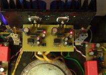
The Zerozone boards have arrived and are up and running. First impression is good, I like the sound, they have not 'failed' any of my test tracks so far.
Had some issues with two resistors not being the same value as the markings on the silkscreen. One was a series resistor on input, and the other in the bias adjustment circuit (connected to bias pot, I think as some kind of voltage divider between rails).
I figured the series resistor on the input was ok. The other one was not, only got the idle current up to maybe 0,1A at max setting.. It was marked 75K, and the supplied resistor was around 500k. I tried the intended value, but only got up to abt 0,7A, so I ended up with 35k, and idling at 1,3A now.
Supply voltage is 19,5V from one laptop brick per channel. I have some C(RL)C filtering too since the boards came with a rectifier and CRC setup.
First one 6800uF, then a small inductor on negative(ground) and a 0R47 on positive rail, after that 4x6800uF+0,5uF polyester.
Tried with only one plain 6800uF first, but sound was suffering, but improved a lot with what I have now. PSU bricks start up fine with this, which I was worried about first.
ZeroZone 'JLH 1969 10W' info
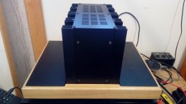
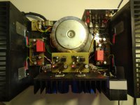
The amp, and especially PSU's, were running a little bit warm for my taste at 1,3A, so today I lowered the current to 1A. It was ok out of the chassis (attached pic of that too), but not a lot of airflow on the PSU's as I installed them.
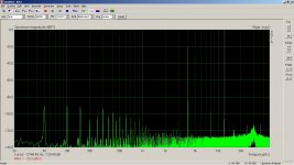
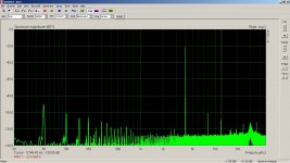
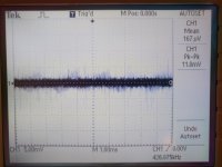
I decided to fo a little bit scientific, so I also tried to do some measurements on it. A lot of factors on the measurements though.. My setup is not very good for amp measurements, I used my 'ARTA box' for speaker measurements, so I only have a fixed attentuator, and since I wanted to measure it at low power levels (2Vpp into 4ohms) where I will use it, the input signal was very low, and that probably affects the ADC in the sound card (Asus Xonar 8ch usb sound card). Please note the -20dB 'reference level'. Measurements are for L & R channels, each averaged three times.
Cables are most likely the cause of the low frequency peaks that are multiples of the grid frequency 50Hz.
Output DAC was running full amplitude, and a Denon receiver was used as preamp.. (another factor). Anyway, results seem ok under the circumstances.
Harmonics went up with higher output, and the third came up to the same level as the second, but higher harmonics were not visible until approaching clipping. The peaks higher up were constant with amplitude, maybe some artefacts from PSU's switching.
I also did a 'reality check' where I compared distortion with 8ohm resistor and some 8ohm workshop speakers (dual tone). They were practically identical, high frequency harmonics were actually slightly lower with the speaker as load.
I could hear a weak beep from the amps around 2,2kHz under load, I suspect there is some resonance in the output caps around that frequency.
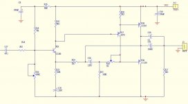
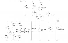
I also attach a schematic for it, probably not much 'JLH' in it?
The amp, and especially PSU's, were running a little bit warm for my taste at 1,3A, so today I lowered the current to 1A. It was ok out of the chassis (attached pic of that too), but not a lot of airflow on the PSU's as I installed them.
I decided to fo a little bit scientific, so I also tried to do some measurements on it. A lot of factors on the measurements though.. My setup is not very good for amp measurements, I used my 'ARTA box' for speaker measurements, so I only have a fixed attentuator, and since I wanted to measure it at low power levels (2Vpp into 4ohms) where I will use it, the input signal was very low, and that probably affects the ADC in the sound card (Asus Xonar 8ch usb sound card). Please note the -20dB 'reference level'. Measurements are for L & R channels, each averaged three times.
Cables are most likely the cause of the low frequency peaks that are multiples of the grid frequency 50Hz.
Output DAC was running full amplitude, and a Denon receiver was used as preamp.. (another factor). Anyway, results seem ok under the circumstances.
Harmonics went up with higher output, and the third came up to the same level as the second, but higher harmonics were not visible until approaching clipping. The peaks higher up were constant with amplitude, maybe some artefacts from PSU's switching.
I also did a 'reality check' where I compared distortion with 8ohm resistor and some 8ohm workshop speakers (dual tone). They were practically identical, high frequency harmonics were actually slightly lower with the speaker as load.
I could hear a weak beep from the amps around 2,2kHz under load, I suspect there is some resonance in the output caps around that frequency.
I also attach a schematic for it, probably not much 'JLH' in it?
Attachments
Last edited:
Too late to edit my post. Correction needed: The Denon receiver was not used as preamp, input volume was adjusted digitally and fed from sound card directly to the amp, so very low bit depth (amplitude) was used both in ADC and DAC.
First of all, I love the design of your amp, it is very successful.
thank you also for taking the time to share the conclusions of your experiences with us.
but it misses a lot of details.
how do you choose your transistors (signal and power) (gain, brand), what have you chosen as output capacitors (brand, voltage, capacity)
what is the supply voltage under load because I made several tests with labtop power supply and I have never had good results compared to a conventional linear power supply (transformer / diode bridge / capacitor / resistance / capacitors ).
I also specify that I have always selected and assembled my jlh "by the ear" and based on the work of Mr. Hood and others who took the following
This is only a kit from China, and the name of the kit is JLH 1969 10W PNP.
V18 PNP Sanken 2SA1216 JLH1969 Class A Power Amp Kit 10W+10W Amplifier Kit | eBay
It should probably have it's own thread, since it is not a 'true' JLH design, which was with NPN output transistors.
I posted here because I started writing about it in this thread.
I have not changed anyting in the kit, except for resistor R19 to 36k to get the idle current up. I did not assemble all the capacitors in the power supply, and substituted one resistor in the CRC to a small inductor.
ok, this is your first JLH amp.
so you still have some development work in front of you.
jlh PNP is a real JLH and the main interest at the time to make a montage in pnp was that the power transistors had more gain.
after other people say that it works better with this polarity but I can not say anything about it.
i have also assembled pnp but i have not kept any transistors in the kit that are probably all fake and badly chosen.
You could also improve on some key components supplied with the kit, which will be cheap to remain competitive. C1 could be larger (say 6800uF) to improve the bass but that also requires more bias current. If you are committed to cheap wall-wart power, 24V bricks come very cheap in up to 4A rating and supply almost enough voltage - probably OK for 4 ohm speakers.
In my view, the JLH design is hard to beat for simplicity and listening pleasure. Most commercial class A designs are now built like a furnace to rival the power of class AB amps but personal listening doesn't need to be that loud nor demand so much wasted power. Think small and enjoy but give it sufficient power to reach useful peak levels without clipping and distortion.
For the JLH class A articles and history lesson plus lots of really useful information on mods and later versions, go to the Class A Amplifier Site, now hosted by Rod Elliott at his ESP site: The Class-A Amplifier Site
If you haven't already done so, you might also like to explore the massive ESP site itself for a ton of other audio projects, design guidelines, PCBs etc.
Thank you for your advice before and now!
The primary reason for building it was to use it for driving 4ohm tweeters in my active crossover setup, so a few watts (max) at high frequencies will be the operating conditions for it (reason for taking the measurement at low voltage, 4kHz into 4ohm).
I think for power, 19,5V and 1A idle current will do for that, and it seems the amp is measuring as expected (?) as it is now, so I plan to run it 'as is' for the moment (too many other projects waiting..). Only thing that bugs me a little is the (mechanical) resonance I could hear around 2k, so I might try another output capacitor, or paralleling it with another one.
The bricks I have are rated over 4A, but built in to the base of the amp, so they hardly get any cooling, but temperature seems ok at 1A. However, I still need to leave them on for a long time to verify that.
The recommended supply voltage for this kit was 15VAC, so that would give just over 20VDC.
I think these JLH's are better for my application than the Pass Aleph Mini's I started out with, -only generating a lot of heat for power I don't need.
Feel free to correct me if I'm wrong!
Last edited:
Hi Rallyfinnen,
A nice build - congratulations.
The 'mechanical resonance' you mentioned could be something like a piece of solid wire or even a fuse.
I had a similar problem which came down to a piece of solid cable from the output fuse holder to the speaker connector: it was only at high outputs and even resoldering it did not make it go away. I just replaced it with insulated stranded copper wire and it was gone.
Maybe if you went around the amp tapping components with a plastic (insulated) screwdriver, you may be able to track it down. This is how I eventually found the cause of my problem.
Best regards
Mike
Ok It took me more then a week to g trough this treath but ok 🙂
I have build a JLH69 when I was in school 12 years ago a s a practical project.
Response measured to 200Khz if I remember correctly.
Transistord where BC560/BD139 and 2N3055
Sounded really nice
So I recently got thinking about the JLH again.
Reading the Class A site it should be possible to get around 50w in 4ohm (high power version)
So if I would build two of those and bridge them I should get around 100w in 8 ohm (and around 340w dissipation 😀)
Next thing I was thinking about is to use more modern output transistors. The 2SC3264 looks nice and are available from profusion
These have lineair gain and have a good contact surface for cooling.
I like the idea of one supply as it protects agains DC. Altough if using it bridged the output capacitors could be left out.
The high power version uses two pairs of output transistors.
What about using more? easier for cooling.
It simulates quite good (4 pairs for one amplifier)
Could be overkill but still.... gives around 25w standing dissipation (worst case) for one transistor.
Any better substitutes then BD139?
For the input I could use bc560 but are there better alternatives?
Then for the single supply version I would also like to use current sources for DC and bias
Then I also notice that you can get maximum power if you put the DC coltage a little bit positive. (probably because of the current sharing emmitor resistances)
when using an output cap ore bridging this is not an issue.
The input comes from a balanced source so I don't need an extra phase splitter to bridge it.
Lots of things to think about....
I couldn't really find if someone tried the 2SC3264 as I was planning to ordering some.
Any better substitutes then BD139?
2SC2682,2SC3423,2SC3505,2SC3116 ,if the current through Tr3 is less than 10mA ;2SC1941,2SC2705,BC337-40,2SC3468
2SC3421 is far worse than all of the above and I do not recommend it.
For the input I could use bc560 but are there better alternatives?
KSA992(2SA992),2SC970(2SA1312 smd)
I couldn't really find if someone tried the 2SC3264 as I was planning to ordering some.
I put 2SC3284 Y and it sounds great, hFE is 180. I think 2SC3264 will sound good too.
It also sounds better with the use of CCSs for input and Tr3.
In my opinion, a great amplifier, with a little improvement, it turns into a real star.
https://www.diyaudio.com/forums/solid-state/3075-jlh-10-watt-class-amplifier-554.html#post5759789
Ok It took me more then a week to g trough this treath but ok 🙂
I have build a JLH69 when I was in school 12 years ago a s a practical project.
Response measured to 200Khz if I remember correctly.
Transistord where BC560/BD139 and 2N3055
Sounded really nice
So I recently got thinking about the JLH again.
Reading the Class A site it should be possible to get around 50w in 4ohm (high power version)
So if I would build two of those and bridge them I should get around 100w in 8 ohm (and around 340w dissipation 😀)
Next thing I was thinking about is to use more modern output transistors. The 2SC3264 looks nice and are available from profusion
These have lineair gain and have a good contact surface for cooling.
I like the idea of one supply as it protects agains DC. Altough if using it bridged the output capacitors could be left out.
The high power version uses two pairs of output transistors.
What about using more? easier for cooling.
It simulates quite good (4 pairs for one amplifier)
Could be overkill but still.... gives around 25w standing dissipation (worst case) for one transistor.
I built such a beasty with 4 output pairs per channel. With 40 volt rails, it gets just over 85 watts into an 8 Ohm load with distortion below 0.1. Into 4 Ohms, Its just under double that.
At about 1 watt is below 0.001% The heatsinks are very generous and I took a mono-bloc approach from power supply onwards - the PSUs including their transformers were in a separate unit.
You mentioned the Class A site, then you will have seen Geoff Moss' high power version. With the same transistors, It can be scaled outwards to 4 pairs (all MJ15003s). Quiescent current is about 3 Amps on mine.
Construction is straight forward as long as you stick to using good quality and genuine parts from a reputable supplier. The 15003s are subject to fakes and I was very lucking in finding a cache of them at Apache Reclamation in Phoenix AZ. (don't bother looking there - I took the lot).
I also found that using the same manufacturer (and if at all possible, the same batch number) for the O/P pairs was good since it gave a high probability of getting matched pairs, although this is not absolutely necessary as JLH and Geoff point out.
Happy soldering
Mike
Last edited:
Hello all,
I am considering building a JlH for powering super tweeters in a system with active crossover. I wonder if the original 1969 schematic would work with a small film capacitor of 2-5uf instead of the large output electrolytic cap?
I have been looking at this kit from Audiophonics:
Amplifier Module Dual Mono Class A Toshiba 2SC5200 2x25W (Pair) - Audiophonics
Is there a chance to get autenthic components in the kit or are they likely to be fakes? In this case it is nice to order good parts right away.
Thanks.
Best Regard,
Anton
Audiophonics is a French, very good company. Not the cheapeat but with a very good customer service. Don't think they will using fake transistors, considering the excellent quality of the other components.
I looked at their web page, and to me it seems many of the amp kits are the same ones you find at ebay (made in china), but with a higher price.
A smaller capacitor on the output should not be a problem, but I think you should anyway filter out low frequencies on the input, or the high voltage swing will make the amp clip pretty quick.
A smaller capacitor on the output should not be a problem, but I think you should anyway filter out low frequencies on the input, or the high voltage swing will make the amp clip pretty quick.
what was the result
not contiunued?
i am very curious, how the story with sublimed JLH ended...
will you share a working complete schematic?
Ralf
not contiunued?
i am very curious, how the story with sublimed JLH ended...
will you share a working complete schematic?
Ralf
I fitted new rads from xeon servers for the higher gain outputs. Will test them this week.
Happy new year to all! And enjoy good quality music in this new year!
Cheers
Sergiu
sublimed JLH1969not contiunued?
i am very curious, how the story with sublimed JLH ended...
will you share a working complete schematic?
Ralf
sorry, for me it seems, that Sergio uses different types of Components.
Maybe i do not exactly understand the amplifier basics
Im allways in search of alternative things- an i landed by your idea.
can the "final" schematic be build as it is.
what replacement transistors can be used -the 2sc are hard to get
best
Maybe i do not exactly understand the amplifier basics
Im allways in search of alternative things- an i landed by your idea.
can the "final" schematic be build as it is.
what replacement transistors can be used -the 2sc are hard to get
best
You can keep the first version , it sounds great . The outputs being dis symmetric , the upper one needs to be faster than the 2n3055 to avoid slew rate failure. Any faster one can do. I chose the fastest I found , but ordinary 2sc5200 is also ok , if casing is not a problem . All the other transistors can be optional . The only imperative is the lower output to remain 2n3055A.
Today I installed voltage regulators in my JLH69 . It is a Walt Jung superreg that I boosted a little. The output voltage is +/-20V and can withstand currents greater than 4A.The voltage drop for good regulation is 4V.
The difference in sound was immediately felt. It was as if I was removing the curtain from the speakers, so many new details came in, the quality of the recording and the studio was exactly felt, the sound stage was literally in my living room, it really sounds wonderful.It played great before, but now it has gone to a higher level.
A few days ago I inserted another RC element into the power supply, so I had 30000+30000+30000uF old + 24000uF new, the resistors between were 3x0,24R, there was a difference on the oscilloscope and also in the sound but not like today with the regulators. At the moment I put jumpers on the resistors so I do not have a voltage drop of 2.5V on them. So I provided a larger voltage drop for the regulators. For the test I will reset it, but then I will have to adjust the regulators to a lower output voltage.
My plan is to make another pair of regulators so that I can separate the power for both channels. I think that will be the final step for this amplifier and I think then I might experience sound enlightenment.🙂
https://refsnregs.waltjung.org/Improved_PN_Regs.pdf
Attachments
Last edited:
- Home
- Amplifiers
- Solid State
- JLH 10 Watt class A amplifier