Hi Peroz,
One reason I recommend the higher speed MJL3281A (NPN) or, I take it the Chinese is a PNP reversal in which case you would need the MJL1302A, or similar (e.g 2SA1943 for PNP, the NPN complement being 2SC5200) is that the high frequency response is limited in the positive direction by the speed of the output transistors because the base drive is bootstrapped, meaning that the output voltage drives a bootstrap connection to keep the drive current to the base as constant as possible. So if you use a slow output transistor , the output risetime will be slow and using original (slow) 2N3055's this would have sounded - indeed, did sound - woolly at the top end.
All of the transistors the other contributors have mentioned -the PNP types are MJ21193, MJ15004, or the NPN types MJ21194, MJ15003 - have a higher frequency response than the original 2N3055. One reason a PNP version might have appeared is that the MJ2955 also has a 4MHz fT- or had; as the latest datasheet from ON states only 2.5MHz for both.
The 30 MHz types will potentially offer a better performance than any, but you would have to be prepared to make some adjustments. As in my earlier notes, a 33pF compensation capacitor is required across the negative feedback resistor to ensure that the amplifier is stable. This may, depending on your set-up, require an additional CR/LR network to prevent oscillations or RF pickup from the speaker leads at the amplifier output. The third adjustment may be to increase the bootstrap resistors to bring the standing current down as a straight substitution could well increase the current due to the higher gain of these devices.
Comparing the performance of the two circuits ("original" '69 using 2N3716 output devices (4 MHz fT); and an MJL3281A output pair with 33pF feedback capacitor) the bandwidth was still extending to 1MHz.
I suspect that your simplest solution is to use 4MHz fT devices with lowish gains (e.g. 20 to 25 min Hfe at 4A, say) which should need little or no adjustments. In many ways the 2N3716 (PNP equivalent 2N3792) is ideal but appear to be obsolete too.
As the MJ15003/4 have an fT of only 2MHz my next best recommendation is to use the MJ21193/4 types which do have fT's of 4Mhz.
John
Hi mjona
And my other reason for recommending the higher speed devices is for lower distortion. I started my investigations into the "original" JLH class A because I was curious about the distortion figures claimed. We already discussed the need for a high gain driver transistor, and while high gain MJ480(1)'s were possible they would have to be selected to be certain.
Using typical gain figures I calculate something like an open loop gain of only 250, and only get something in the order of 600 that JLH mentioned with the highest gain devices in each stage. The simulated (typical) distortion figure at just under 10W is 0.25% (at 20kHz) with a BC557, BD139 and 2N3716 line-up. But being Class A this does reduce with lower power levels.
One surprising factor is that the feedback "gain" resistor of 220 ohms is that high. If the input transistor operates at 300uA then the input impedance to the emitter is 84 ohms or so, and therefore while 220 ohms gives substantial local feedback a "free" increase in gain is possible by using a lower value such as 82 ohms which matches the hib value and below which is diminishing returns. The feedback resistor would therefore have to be 1k but that is a trivial change. With this mod, 2x increase in loop gain is possible.
Due to the linearity of the gain with current in the MJL3281A's the output stage distortion is at least 3x lower than using older e.g. 2N3716's.
As simulated, the 10W distortion figure with MJL3281A change alone is 0.15% (at 20kHz) and with the feedback/grounding resistor changes this reduces to 0.06%.
My final point is that while I agree with your observations that having a low fT stage within a three-stage circuit is usually stable, I counter that with say devices having fT's in the 5-10Mhz range, at what might be the high frequency roll-off points the driver transistors will have significant phase shift even for 100MHz devices. This pushes the overall phase margin to less than 90 degrees whereas with the compensation capacitor on the MJL3281A configuration, the phase lead this affords compensates nicely and gives a 6dB/octave roll off.
I tried simulating both circuits with a 1uF capacitor in parallel with the 8 ohm load without inductors etc. in the output. The compensated MJL3281A had less ringing and a faster response than the 2N3716 version.
John
Thanks to all of you for your kind input. I find it still a lot to process and will study it further in the next couple of days.
Whoa, John, this was reading scientifically already🙂
You were asking which Chinese amps I have, it's these:
Hi Peroz,
One reason I recommend the higher speed MJL3281A (NPN) or, I take it the Chinese is a PNP reversal in which case you would need the MJL1302A, or similar (e.g 2SA1943 for PNP, the NPN complement being 2SC5200) is that the high frequency response is limited in the positive direction by the speed of the output transistors because the base drive is bootstrapped, meaning that the output voltage drives a bootstrap connection to keep the drive current to the base as constant as possible. So if you use a slow output transistor , the output risetime will be slow and using original (slow) 2N3055's this would have sounded - indeed, did sound - woolly at the top end.
All of the transistors the other contributors have mentioned -the PNP types are MJ21193, MJ15004, or the NPN types MJ21194, MJ15003 - have a higher frequency response than the original 2N3055. One reason a PNP version might have appeared is that the MJ2955 also has a 4MHz fT- or had; as the latest datasheet from ON states only 2.5MHz for both.
The 30 MHz types will potentially offer a better performance than any, but you would have to be prepared to make some adjustments. As in my earlier notes, a 33pF compensation capacitor is required across the negative feedback resistor to ensure that the amplifier is stable. This may, depending on your set-up, require an additional CR/LR network to prevent oscillations or RF pickup from the speaker leads at the amplifier output. The third adjustment may be to increase the bootstrap resistors to bring the standing current down as a straight substitution could well increase the current due to the higher gain of these devices.
Comparing the performance of the two circuits ("original" '69 using 2N3716 output devices (4 MHz fT); and an MJL3281A output pair with 33pF feedback capacitor) the bandwidth was still extending to 1MHz.
I suspect that your simplest solution is to use 4MHz fT devices with lowish gains (e.g. 20 to 25 min Hfe at 4A, say) which should need little or no adjustments. In many ways the 2N3716 (PNP equivalent 2N3792) is ideal but appear to be obsolete too.
As the MJ15003/4 have an fT of only 2MHz my next best recommendation is to use the MJ21193/4 types which do have fT's of 4Mhz.
John
Whoa, John, this was reading scientifically already🙂
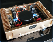
You were asking which Chinese amps I have, it's these:
Attachments

Well, peroz, that is an interesting picture. The output transistors appear to be genuine ST 2N3055's and fairly recent (2009?). These are NOT the old slow devices but will have a high frequency response of around 3MHz. I have built one of my better class AB 50W amplifiers using the same device and PNP complement. I measured a low frequency gain fall-off on my samples at 60kHz, which basically means that the gain starts to reduce well above the audio band.
I think that your JLH design with these will not sound too bad at all. I suspect that many people who compare MJ21194's with 2N3055's are comparing the old slow 3055 types which have not been made as such for perhaps 20 years now, but may have been used in several JLH amplifiers maybe when the MJ21194 devices appeared and would have made a big difference. However, you could try MJ21194's as they will have lower distortion due to a better gain linearity than the 3055, even though the gain will be around the same as the 3055.
John
Hi mjona
And my other reason for recommending the higher speed devices is for lower distortion. I started my investigations into the "original" JLH class A because I was curious about the distortion figures claimed. We already discussed the need for a high gain driver transistor, and while high gain MJ480(1)'s were possible they would have to be selected to be certain.
Using typical gain figures I calculate something like an open loop gain of only 250, and only get something in the order of 600 that JLH mentioned with the highest gain devices in each stage. The simulated (typical) distortion figure at just under 10W is 0.25% (at 20kHz) with a BC557, BD139 and 2N3716 line-up. But being Class A this does reduce with lower power levels.
One surprising factor is that the feedback "gain" resistor of 220 ohms is that high. If the input transistor operates at 300uA then the input impedance to the emitter is 84 ohms or so, and therefore while 220 ohms gives substantial local feedback a "free" increase in gain is possible by using a lower value such as 82 ohms which matches the hib value and below which is diminishing returns. The feedback resistor would therefore have to be 1k but that is a trivial change. With this mod, 2x increase in loop gain is possible.
Due to the linearity of the gain with current in the MJL3281A's the output stage distortion is at least 3x lower than using older e.g. 2N3716's.
As simulated, the 10W distortion figure with MJL3281A change alone is 0.15% (at 20kHz) and with the feedback/grounding resistor changes this reduces to 0.06%.
My final point is that while I agree with your observations that having a low fT stage within a three-stage circuit is usually stable, I counter that with say devices having fT's in the 5-10Mhz range, at what might be the high frequency roll-off points the driver transistors will have significant phase shift even for 100MHz devices. This pushes the overall phase margin to less than 90 degrees whereas with the compensation capacitor on the MJL3281A configuration, the phase lead this affords compensates nicely and gives a 6dB/octave roll off.
I tried simulating both circuits with a 1uF capacitor in parallel with the 8 ohm load without inductors etc. in the output. The compensated MJL3281A had less ringing and a faster response than the 2N3716 version.
John
Thanks John,
I am interested in your result and wonder if you can post the simulations.
I have been looking at the challenge of working with MJL21194's as outputs - simulating the circuit with 2N3906 in the first stage and BD139 in the second stage voltage amplifier-phase split section.
This is mainly an exercise to satisfy my curiosity since MJL21194's are claimed to be linear - albeit with some sacrifice in current gain.
My starting plan was to run the BD139's at an increased collector current - this in theory would result in a proportionate increase in voltage gain provided the collector load was relatively unaffected. This should increase the open loop bandwidth allowing greater use of nfb.
I don't rely on simulations but they can be a useful guide that avoids going down a wrong path. In this case I think the results support the theory.
Specifically, I increased the collector current of the BD139 to 17 m.a. from the level of 12 m.a. in your circuit - this by reducing R2 from 470R to 300R. A consequence of this was the output stage current increased to 1.28A - a figure higher than your implementation but only a little higher than recommended by Hood.
I don't see that as necessarily bad since Hood's figure was to allow for variability in speaker loads.
I made some changes to the input bias scheme and rail decoupling resistor values to get for 13 volts at the output before the 2200uF cap.
I added a zobel on the output of 8R in series with 100n. A series .22R buffer resistor follows the zobel network.
I added a resistor capacitor series combination of 220R and 330pF in parallel with the 2.7k feedback resistor to convert the return arm to a step response form.
I ran a square wave test on this with a load of 8R with 2.2uF in parallel. There are no overshoots or glitches in the wave form.
The closer on this was the 0.22R buffer resistor - without this there was a small glitch at the leading edge on negative output excursions.
I included one on my 1969 build and the memory of this prompted me to try it in the simulation.
Hood published pictures of oscilloscope wave-form images and these look better than the ones I have simulated. He must have gotten some things right.
Michael
Because of the very low cost of kits like the one shown above by peroz, most builders will sensibly take that route and likely also begin with current production STmicro 2N3055 output transistors. Some DIYs may then be locked into TO3 style output devices with few realistic options outside the 3-4 MHz Ft range. Frankly though, I don't hear any benefits from going beyond that in trying to reduce the very distortion that devotees of the amplifier often seek to enhance rather than eliminate, whether they realise it or not.
I have scratch-built several of these amplifiers over 30 odd years, using the most basic of assembly techniques and I've always had a liking for the sound quality, despite the unpopularity of class A and capacitor output. Perhaps a more significant downside was low power, since over much of that period, anything less than 100W power had been deemed unworthy. Only the rebirth of the tube age has brought people back to the reality of how much power we don't need.
It's interesting that the historic and nostalgic aspects of this project run so strongly both in technical discussions and DIY enthusiasm. I wonder if JLH himself would not be rolling with laughter at the thought of so many, still keen to hear this ancient gem in action and then so passionate about using it as their daily go-to amplifier. He might be flattered, but as an engineer and designer of many other technically superior projects, I doubt he would be so proud of this one's continued dominance and legendary DIY status.
FWIW, I recently bought a similar Chinese kit based product with the same transistor lineup, already built in a flashy case, working and replete with volume control for just US $123. YMMV but I could not build it myself for less, even after freight costs were added.
Attachments
Hi Ian, as a matter interest can you post the link to your Ebay seller of this amp. It would be interesting to see what else he has. Kevin
Thats the one I bought also but changed the input cap on it. [emoji846] searching eBay now I found this http://www.ebay.com/itm/Nobsound-HD...reo-AMP-DIY-/251547956833?hash=item3a916d3661
Sent from my iPhone using Tapatalk
Sent from my iPhone using Tapatalk
Hi Peroz,
I used the MJ15003 and it sound great for my taste.
Have a look here for Output transistors; The Class-A Amplifier Site - JLH Class-A Update
This is what I'm refering to;
''Output transistors.
The 2N3055s were replaced with MJ21194. In comparison with these the 2N3055s sound grey and rather diffused with less sense of authority, less detail and a more prominent treble quality. In contrast, the MJ21194s have a noticeably firmer sound with more ambience in the treble and greater detail. More natural generally. Reluctantly, they were removed from the circuit due to a faint hum which was not present with the 2N3055s.
Wanting to try something else, and now with the strong impression that the 2N3055s were less than ideal, I tried some MJ15003s.
This time, a substantial improvement over the 2N3055s. The MJ15003's bass is both tauter and more authoritative, with cleaner treble and greater textural detail.''
p.s. The above is for the bipolar JLH version, for my JH 1969 I used the ON semi NJW21194.
BR,
Eric
Hi !
On my jlh 1969 amp, the 2SD1047 were a big improvement over the MJ15003 and more noticeable than the improvement between 3055 and 15003 !
The hum with MJ21194 was certainly the cause of an oscillation.
Guillaume
Last edited:
I don't know that I could stare at the "Nobsound"Hi Ian, as a matter interest can you post the link to your Ebay seller of this amp. It would be interesting to see what else he has. Kevin
 brand too long but actually, I bought through Aliexpress who are generally cheaper for the same goods but there may be more risk, I understand. The price has crept up a little, despite the current discount. I couldn't complain about the service and delivery time though - just the fact that the heatsinks are bolted to the thick front panel and eventually, the fascia and even the nicely copied RK27 volume control copy and aluminium knob become quite warm to hot, unless you give it plenty of air from below. Raising it about 30mm on open mesh or tall feet make a lot of difference but perhaps a plinth with slow spinning fan is better at this time of year in Oz, when p.m. room temperature already nudges 35C.
https://www.aliexpress.com/item/nov...32241616505.html?spm=2114.13010608.0.0.sEAmHE
Well, peroz, that is an interesting picture. The output transistors appear to be genuine ST 2N3055's and fairly recent (2009?). These are NOT the old slow devices but will have a high frequency response of around 3MHz. I have built one of my better class AB 50W amplifiers using the same device and PNP complement. I measured a low frequency gain fall-off on my samples at 60kHz, which basically means that the gain starts to reduce well above the audio band.
I think that your JLH design with these will not sound too bad at all. I suspect that many people who compare MJ21194's with 2N3055's are comparing the old slow 3055 types which have not been made as such for perhaps 20 years now, but may have been used in several JLH amplifiers maybe when the MJ21194 devices appeared and would have made a big difference. However, you could try MJ21194's as they will have lower distortion due to a better gain linearity than the 3055, even though the gain will be around the same as the 3055.
John
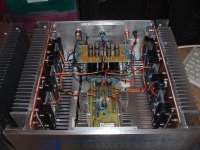
These are genuine transistors. Because I destroyed the ones that came with the kit with clumsy mounting... These new ones costed more than the complete kit. 😀
I'm glad I apparently don't necessarily need to change the transistors. Are there any other passive components that are worth changing to top quality? Some people here write about input caps... how would I go about that?
Often we fit retrofit MKP polypropylene film caps in place of electrolytics at the input stage. These are more expensive but much larger than the specified original polyester film MKT type in the JLH amplifier. I believe that the 1uF types supplied in that kit are MKP anyway, though I notice some folk here trash that brand because it is of Chinese origin and cheaper than traditional manufactures. Don't be fooled by price and source of components without proof of a significant difference though. These caps are already way above the needs of the application and you don't need to change them. Aesthetics are another matter but once the cover is on, does it really matter if you didn't pay $20 for a $2 product?.... Are there any other passive components that are worth changing to top quality? Some people here write about input caps... how would I go about that?
Someone will always tell you that you should buy what they already paid too much for because what they built with it sounded good to them, whether it is an oil-filled paper capacitor from 60 years ago or the newest brand, hand made film/foil cap. intended for pulse generators. Some really are good, genuine products - at a price! This is audiophile territory and there are many sharks out there also selling snake oil as extraodinary quality product and lots of gullible people who swallow any testimonials as fact rather than try to understand what tests and specifications mean.
Note that very large, unshielded caps might seem like a cool idea but they are often detrimental to audio because at the sensitive input stage, they tend to be "aerials" for any radiated noise including RFI, power supply switching noise and general environmental electronic noise. You don't necessarily hear any added noise but the resulting sound degradation can be disappointing.
May I suggest something? Don't change anything until you are completely familiar with the sound quality over as wide a range of your music as possible. Make comparisons with other amplifiers if you have any at your disposal and try to identify anything different in the sound but you need to use a sound level meter or an improvised one using an audio tone, a fixed microphone and recorder, to ensure that you have exactly the same output levels for a proper comparison - even small errors with sound levels will confuse a listening test to the point being inconclusive and useless.
Anyway I would change the input cap to something better [emoji4]
Sent from my iPhone using Tapatalk
Sent from my iPhone using Tapatalk
Well stated Ian, as usual. I agree with all you just stated.
That complete amp you linked is $200 to the USA so not a huge bargan. Especially when taken into account that the heatsinks are really too small.
That complete amp you linked is $200 to the USA so not a huge bargan. Especially when taken into account that the heatsinks are really too small.
Anyway I would change the input cap to something better [emoji4]
Sent from my iPhone using Tapatalk
If i don't make a mistake, the input capacitor is already a MKP type (WIMA).
There's something better than Wima for sure, but, Wima MKP are not bad at all.
If your amp is a 1969 type with output capacitor, i suggest you have to change the output capacitor at first.
Last edited:
JLH Class A amp - bits and bobs
Hi All,
Having built various version of the JLH Class A amp, I thought I would contribute to the knowledge pool on this with a few suggestions that I am writing up later in a complete article.
I have experimented with the several variations of the amp and find the Geoff Moss version to be the most pleasant to my ears and the certainly the most builder friendly.
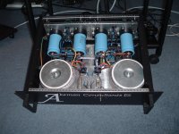
I use the high-power version that employs 4, MJ15003 transistors in the output stage and built 2 mono-blocs with independent power supplies in a separate case and connected by an umbilical cable to the amp chassis that also contains further smoothing and a capacitance multiplier.
There are a couple of modifications I have tried that can be retrofitted to the Geoff Moss version that can reduce the distortion quite radically to a point where the 2nd harmonic component is down at around 0.0035%. I can't measure the 3rd harmonic value as it is below the capability of my measuring test gear so I assume it is down in the noise somewhere.
The modification is around the Voltage Amp stage: changing that to a simple Sziklai pair with unity gain, drops the distortion down from 0.09% to 0.03%, which is quite good, however it starts to rise a bit at about 20KHz to about 0.07%
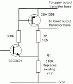
Changing the S-Pair to provide a bit of gain as in the attached diagram, then drops the distortion down and order of magnitude to about 0.0035%, again rising back up to about 0.06% at 20KHz or so. Use high Hfe devices if you can.
I have found the modification does not need any compensation and on my pcb layout is unconditionally stable with a minute overshoot on a 10KHz square wave. I did have a few problems when experimenting on my original PCB that had the mods on a small daughter board, but a 10pF from base to collector of the NPN solved that as did a new pcb layout without the 10pF cap to include the S-pair.
Kind regards
Mike
Hi All,
Having built various version of the JLH Class A amp, I thought I would contribute to the knowledge pool on this with a few suggestions that I am writing up later in a complete article.
I have experimented with the several variations of the amp and find the Geoff Moss version to be the most pleasant to my ears and the certainly the most builder friendly.
I use the high-power version that employs 4, MJ15003 transistors in the output stage and built 2 mono-blocs with independent power supplies in a separate case and connected by an umbilical cable to the amp chassis that also contains further smoothing and a capacitance multiplier.
There are a couple of modifications I have tried that can be retrofitted to the Geoff Moss version that can reduce the distortion quite radically to a point where the 2nd harmonic component is down at around 0.0035%. I can't measure the 3rd harmonic value as it is below the capability of my measuring test gear so I assume it is down in the noise somewhere.
The modification is around the Voltage Amp stage: changing that to a simple Sziklai pair with unity gain, drops the distortion down from 0.09% to 0.03%, which is quite good, however it starts to rise a bit at about 20KHz to about 0.07%
Changing the S-Pair to provide a bit of gain as in the attached diagram, then drops the distortion down and order of magnitude to about 0.0035%, again rising back up to about 0.06% at 20KHz or so. Use high Hfe devices if you can.
I have found the modification does not need any compensation and on my pcb layout is unconditionally stable with a minute overshoot on a 10KHz square wave. I did have a few problems when experimenting on my original PCB that had the mods on a small daughter board, but a 10pF from base to collector of the NPN solved that as did a new pcb layout without the 10pF cap to include the S-pair.
Kind regards
Mike
Attachments
Impressive size and build! - way beyond the constraints of the original design and with such low distortion, it won't be sounding much like the venerable Williamson tube amp.
When you say it's more builder-friendly, what aspects are you considering - parts availability, size, ease of access etc? It sure won't have been easy on the wallet.
When you say it's more builder-friendly, what aspects are you considering - parts availability, size, ease of access etc? It sure won't have been easy on the wallet.
Hi Terry, good to hear from you and thanks for the kind words. Yes, I wound up paying US $182, delivered to my door, with a courier option. After I cranked through the sums, even using cheap components (which incidentally are mostly fine for JLH) my DIY costs were going to be more like $260. Then I still had to drill and cut holes, assemble, wire up and finish it with a good WAF, as it was destined as a gift for a friend who no longer can do the DIY work.....That complete amp you linked is $200 to the USA so not a huge bargan.....
Long story short, he's ecstatic for the moment but like any curious newbie, reads forums full of dubious parroted comments about the night and day improvements in swapping caps - always just caps because they're easy to identify and replace but he's now a prime target for fakes and exotic parts sellers 😉
Last edited:
Hi All,
Having built various version of the JLH Class A amp, I thought I would contribute to the knowledge pool on this with a few suggestions that I am writing up later in a complete article.
I have experimented with the several variations of the amp and find the Geoff Moss version to be the most pleasant to my ears and the certainly the most builder friendly.
I use the high-power version that employs 4, MJ15003 transistors in the output stage and built 2 mono-blocs with independent power supplies in a separate case and connected by an umbilical cable to the amp chassis that also contains further smoothing and a capacitance multiplier.
There are a couple of modifications I have tried that can be retrofitted to the Geoff Moss version that can reduce the distortion quite radically to a point where the 2nd harmonic component is down at around 0.0035%. I can't measure the 3rd harmonic value as it is below the capability of my measuring test gear so I assume it is down in the noise somewhere.
The modification is around the Voltage Amp stage: changing that to a simple Sziklai pair with unity gain, drops the distortion down from 0.09% to 0.03%, which is quite good, however it starts to rise a bit at about 20KHz to about 0.07%
Changing the S-Pair to provide a bit of gain as in the attached diagram, then drops the distortion down and order of magnitude to about 0.0035%, again rising back up to about 0.06% at 20KHz or so. Use high Hfe devices if you can.
I have found the modification does not need any compensation and on my pcb layout is unconditionally stable with a minute overshoot on a 10KHz square wave. I did have a few problems when experimenting on my original PCB that had the mods on a small daughter board, but a 10pF from base to collector of the NPN solved that as did a new pcb layout without the 10pF cap to include the S-pair.
Kind regards
Mike
Congratulations for this superb amp!
Is it JLH 2005 ?
Hi folks,
thanks for the kind words. I really do like the supportive nature of this forum. 🙂
It is based on the updated Geoff Moss version using transistor current sources for the Iq and Voffset adjustments and is pleasant to my ears: the amp seems to grab the speakers by the scruff of the neck and control them, particularly at the bottom end. The opening track of John Williams Jurassic Park on vinyl is something to die for. The brass and bass are just unbelievable clear and precise.
Is is build friendly in that if you use 22 turn pots for the adjustments and take your time (Also a current limited power supply during testing), it always seem to work first time. It's also simple in design and I have a pet theory that the smaller the number of amplifying stages, the better it is.
It wasn't too expensive to build. The main cost was the two Chinese cases and the transformers, but I did enjoy building it.
Best regards and happy listening
Mike
- Home
- Amplifiers
- Solid State
- JLH 10 Watt class A amplifier