Adjustment Instructions
See my post 2584 for instructions I received from Geoff Mass as to how to set the two adjustments:
http://www.diyaudio.com/forums/solid-state/3075-jlh-10-watt-class-amplifier-259.html#post3218398
See my post 2584 for instructions I received from Geoff Mass as to how to set the two adjustments:
http://www.diyaudio.com/forums/solid-state/3075-jlh-10-watt-class-amplifier-259.html#post3218398
OK, I found this which shows it as a single output 😱
HY3005: 150W Single Output Benchtop Power Supply: Jameco Benchpro
HY3005: 150W Single Output Benchtop Power Supply: Jameco Benchpro
What it would seem like, and again just an opinion, is that your bias current is set higher than the current limit of the power supply or Q6 is short circuit and therefor the PSU simply cuts the POS 22V. Try lowering the bias to only a few mA and look see what the supply does.
Well done Mooly! who else would think of looking it up. I would still be keen to know where the +22 and -22V measurements came from on the edited circuit. Unless he has two of those in series.
Last edited:
Yes, we seem to have a fundamental problem with the PSU arrangements 🙂
I'm going to have to leave it for tonight but I'm sure the good folk on here will explain why its not suitable... abpea, you would actually need two of those power supplies to make a dual rail supply that this version of the JLH needs.
I'm going to have to leave it for tonight but I'm sure the good folk on here will explain why its not suitable... abpea, you would actually need two of those power supplies to make a dual rail supply that this version of the JLH needs.
Nico I only have one one of these power supplies that I've been using on this build. Evidently one is not enough... 🙁
Mooly I understand now why I need an additional power supply. No wonder I couldn't get any voltage on the second rail.
Building amps is a humbling experience...
Building amps is a humbling experience...
Aha, that is the problem all along.
That particular version of the JLH is meant for a dual supply. What you have is a single supply.
I will also have sign off now but will have a look see what transpired. I think your best bet is to go with the 1969 design or we need to construct a dual PSU for your purpose. Still I think a proper PCB will be worthwhile.
EDIT: No worries we all started somewhere!
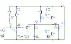
Since your amp is a little messy, I suppose we can modify that one to operate on a single supply, you would need to find a capacitor of at least 2200uF at 35V and of course one to decouple R6 as was described earlier.
I know you are itching to make it work now because the sun is shining outside (here it is not) 🙂
I know you are itching to make it work now because the sun is shining outside (here it is not) 🙂
If you cannot wait, here is a start.
EDIT Sorry I did not bother to use the same component numbers as I do not have time, work it out I am sure you will have success.
EDIT Sorry I did not bother to use the same component numbers as I do not have time, work it out I am sure you will have success.
Attachments
Last edited:
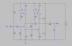
If you want to use single supply, why not build the JLH 1969? It uses just one rail and 22V is enough. It is a great sounding amp as well. It just needs the additional output cap. I think the parts you have will suffice for the rest.
Here is a layout you could follow with your PTP.
https://theslowdiyer.files.wordpress.com/2014/06/minijlh1969pcb-1.png
Here is a layout you could follow with your PTP.
https://theslowdiyer.files.wordpress.com/2014/06/minijlh1969pcb-1.png
Last edited:
Terry. the layout does not show the ground connections, I take it as a copper pour on the bottom layer.
Yeah that looks right. I guess he will have to connect those to his ground wire. I probably should have looked longer 😀
Member
Joined 2009
Paid Member
I don't believe your measurements abpea. Gareth, before analyzing the problem let him remeasure, there is more than meets the eye going on here.
Well it turns out my analysis was correct (this time at least !) as there is no proper 'ground' because there is no 'centre tap' at the supply.
I don't think a PCB is needed, it's plenty fine to do it on photo-board. My amp is on veroboard and works just fine.
Agree with the suggestion that you go with the 1969 version, single rail with output capacitor. It sounds plenty superb with single rail. I would recommend you consider the addition of an RC filter to the supply rail feeding the phase splitter or if no large C available use a capacitance multiplier in the rail (both ideas are a new twist on the basic circuit that I introduced in my version 'TGM9' linked above) since it acts to improve the PSRR of the amplifier without any obvious downside (needs a large value C).
There is no way this circuit is going to be dc stable without a capacitor in series with R6.
The circuit as-shown without the cap is correct, you need to go and read up on it - a set of articles on Jeff Moss web-site dedicated to Class A amplifiers where the original JLH96 was further tweaked to remove the cap (some people are particularly allergic to caps). Personally, I think the 1996 circuit with no feedback cap and with dual rails is not the best starting point for a beginner - too tetchy.
Last edited:
Before you would consider building again, or buying another power supply, maybe you could test it first with one lab supply.
Only need to add one resistor at the input and one capacitor at the output.
Once it works and you like the results, you would want to build a proper dual-rail power supply anyhow.
Patrick
Only need to add one resistor at the input and one capacitor at the output.
Once it works and you like the results, you would want to build a proper dual-rail power supply anyhow.
Patrick
Attachments
Member
Joined 2009
Paid Member
Gareth, I should have know that you were coming to steal the lime light away from us poor sods in the dark!!
BTW: Should you not be losing some of those baby teeth in your Avatar?
BTW: Should you not be losing some of those baby teeth in your Avatar?
Member
Joined 2009
Paid Member
I would not think of you in the dark, last time I checked Hugh Dean had heaped a lot praise on your skills and he knows a thing or two about such things !
I'm no spring chicken, but who wants an older and greying avatar 🙂
I'm no spring chicken, but who wants an older and greying avatar 🙂
- Home
- Amplifiers
- Solid State
- JLH 10 Watt class A amplifier