Thanks Mooly.
I'm checking R10 and I get the same voltage on both sides... time to replace?
Nope, same voltage on both sides suggests its OK. Check the transistors out of circuit. John makes a very valid point over the possibility of zapping transistors due to there being no limiting resistor in series with the pre-sets. If that has happened then the pre-set itself could be damaged too due to excess current flowing in the tiny moving wiper contact.
Has anyone made a table of test points/voltages at a certain rail voltage for the JLH96 that I could use?
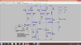
Here we go, running on -/+22 volts. When looking for faulty transistors by voltage measurement, a good clue is to check the base/emitter voltage by reading across the junction. You'll notice that all the B-E junctions have around about 0.6 to 0.7 volts across them. Don't worry about exact voltages... you are looking for major discrepancies such as 5 volts on the base and (say) 2 volts on the emitter which would indicate an open circuit device.
Attachments
I'll look in tomorrow 🙂
All those voltages are measured from ground, and so just by checking and comparing those you should find a point where something goes wildly astray... typically across a B/E junction and even if they are all wrong there will be a point in the circuit that shows a non valid result across a transistor.
Good luck.
Thanks Mooly.
I'm checking R10 and I get the same voltage on both sides... time to replace?
That just means There is no bias. R10 is likely OK.
R10 has no DC current thru it due to C3, therefore no voltage drop.
Craig, also in Victorville
Craig, also in Victorville
Mooly (and everyone else who has given me some feedback) thanks again for the voltage chart, it has been really useful and helpful! Much, much appreciated my friend.
So I spent a lot of time checking voltages according to the chart you gave me. Unfortunately everything seems to be in order. Nothing obvious that jumps out at me.
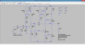
One thing I find curious is I have an 8 ohm resistor across the output and I can measure ~330 mv on R8 (see circuit below) but I can't read any voltage across the output.
About the only thing I haven't changed out yet are VR1 and VR2. They certainly could be fried. I'll do that tomorrow morning.
Thanks again to all of you. Your help and advice is priceless to this new amp builder and is very much appreciated.
I'll get back to it tomorrow, now it's time for a cocktail!! 🙂
So I spent a lot of time checking voltages according to the chart you gave me. Unfortunately everything seems to be in order. Nothing obvious that jumps out at me.
One thing I find curious is I have an 8 ohm resistor across the output and I can measure ~330 mv on R8 (see circuit below) but I can't read any voltage across the output.
About the only thing I haven't changed out yet are VR1 and VR2. They certainly could be fried. I'll do that tomorrow morning.
Thanks again to all of you. Your help and advice is priceless to this new amp builder and is very much appreciated.
I'll get back to it tomorrow, now it's time for a cocktail!! 🙂
You shouldn't read any DC voltage across the load resistor at the output unless you have and offset, which you don't want. You should only read AC voltage across it if you are feeding a signal into the input. You are likely just fine.
I think we are looking at different schematics. Mooly's schematic has different part numbers.
R10 has no DC current thru it due to C3, therefore no voltage drop.
Craig, also in Victorville
I think we are looking at different schematics. Mooly's schematic has different part numbers.
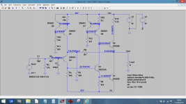
I've altered the component references to match the earlier diagram.
The important things to check are,
1/ That VR1 and VR2 are intact. This applies particularly to VR2 where any dead spot or anything intermittent with the wiper would cause a large and destructive current to flow in the base emitter junction of Q7 and that would carry through to Q8.
You can only test these resistors with Q5 and Q7 removed. VR2 should never be turned so far that it effectively shorts out the B-E junction of Q7 because that would cause a large destructive current to flow in Q8. The same applies to VR1 because there is a low impedance path via Q6, Q4and then the B-E junctions Q3 and Q1 to the negative rail.
So never turn these pots down to the low resistance end of their range. If you replace them then set them midpoint to begin with.
Assuming these resistors are OK then you should measure around 0.65 volts across each.
Every one of the transistors should have this magic 0.65 volts or so across their B-E junctions. For the NPN devices the base will be the more positive. For the PNP's the emitter is the more positive.
If you get stuck then copy the second image here and write your measured voltages onto the diagram and we'll see where the problem is. Readings to a couple of decimal places are fine.
Attachments
Member
Joined 2009
Paid Member
You might find the driver stages need to supply significantly more current to bias four output devices.
Why not simulate it and see how it behaves ?
My version has 4 pairs of 2N3055's per channel and the driver stage appears to have no issue at d.c. In fact, with so many output devices you can bias the amplifier so that it is at the peak Hfe of the output transistors (as recommended by Hiraga in his Le Monstre article) and for normal music you'll have no issues with beta-droop.
Of course at h.f. you have more base capacitance to drive but again I don't have any complaints. I did try using a CFP phase splitter to reduce the drive impedance but it did NOT sound as nice so I reverted back to a single device. It's still in use as my main amplifier, having edged out my 6AS7 SET amp for prime spot in the living room.
see here: http://www.diyaudio.com/forums/solid-state/268846-tgm9-my-version-jlh-69-class-amplifier.html
Attachments
Another question, what is the proper way to measure current on R10?
Do I measure current across R10 or do I place one probe on the negative rail and the other on R10?
Thanks -
Bruce
Do I measure current across R10 or do I place one probe on the negative rail and the other on R10?
Thanks -
Bruce
Looks good  The drive requirements of the outputs are not insubstantial but perhaps modern devices go some to make up for that (compared to the original 2N3055's).
The current flowing in VR2 sets the ultimate base drive current available to the outputs, but being Class A you will have set the output stage current to an appropriate level anyway to ensure you can deliver full output into your chosen load impedance.
I agree that its a great amp.
The drive requirements of the outputs are not insubstantial but perhaps modern devices go some to make up for that (compared to the original 2N3055's). The current flowing in VR2 sets the ultimate base drive current available to the outputs, but being Class A you will have set the output stage current to an appropriate level anyway to ensure you can deliver full output into your chosen load impedance.
I agree that its a great amp.
Another question, what is the proper way to measure current on R10?
Do I measure current across R10 or do I place one probe on the negative rail and the other on R10?
Thanks -
Bruce
Just measure the voltage across the resistor and then calculate the current using ohms law (I= V/R). So for 2 amps current (for example) you should see 0.66 volts across the 0.33 ohm.
- Home
- Amplifiers
- Solid State
- JLH 10 Watt class A amplifier