A question for @Perry Babin or other gurus here - I'm working on a JL 1000/1 that had corrosion and other damage in the startup circuit area, on the daughter board in the area that sits above the power terminals (pretty common, from my understanding).
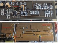
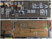
I repaired all of the continuity issues I could find - see the pics. The ground plane was actually burnt open in three locations on the daughter board due to the previous owner directly gouging into the ground plane from the positive terminal below (I think). I also found two open traces in the area due to corroded vias, and one blown NPN transistor (original part was marked ZC) sitting near the LM324.
After fixing these continuity issues and replacing the NPN, when I place the daughter-board back onto the main amp board and apply remote, the green led lights right away, but nothing else 'starts' until an approximate 15 second delay. The red and yellow leds flash for a moment when this happens. When I place the daughter board into a known good 1000/1 (all boards same revs) I get the same delay, whereas when using the good amp's normal daughter board the amp 'starts' in less than 3 seconds as expected.
I also noticed that in the 'bad' amp the supply voltage on pin 6 of the header (in my pic, the pin with the orange jumper wire soldered on) does not pull low when remote is removed - it stays up as long as main +12V to battery is present. Whereas in the good amp it pulls low as soon as remote is removed. It looks like this pin is fed through a 4.7ohm resistor from the positive supply plane after the choke on the main board, so maybe this could be a clue...
Any advice would be appreciated. Has this delayed start behavior been seen by others?
Thanks, Cheers
Attachments
Is there any green powdery substance in any of the vias in that area?
DCV on all terminals of the LM324? Copy and paste the following list and fill in the blanks. If there is no blank space after the colon, add one between the colon and the numbers you enter. It makes it much easier to read.
Pin 1:
Pin 2:
Pin 3:
Pin 4:
Pin 5:
Pin 6:
Pin 7:
Pin 8:
Pin 9:
Pin 10:
Pin 11:
Pin 12:
Pin 13:
Pin 14:
I've since cleaned up the area quite a bit, but I don't recall white powder. There was a lot of green corrosion in both of the bad vias. I've since checked conductivity through the vias on that side of the board.
For the LM324:
Pin 1: 12.6
Pin 2: 3.7
Pin 3: 6.4
Pin 4: 14.0
Pin 5: 6.2
Pin 6: 5.1
Pin 7: 12.7
Pin 8: 12.8
Pin 9: 5.7
Pin 10: 10.2
Pin 11: 0.0014 (Gnd)
Pin 12: 3.7
Pin 13: 5.0
Pin 14: 1.0
FYI - my bench supply is fixed at 14.4V
For the LM324:
Pin 1: 12.6
Pin 2: 3.7
Pin 3: 6.4
Pin 4: 14.0
Pin 5: 6.2
Pin 6: 5.1
Pin 7: 12.7
Pin 8: 12.8
Pin 9: 5.7
Pin 10: 10.2
Pin 11: 0.0014 (Gnd)
Pin 12: 3.7
Pin 13: 5.0
Pin 14: 1.0
FYI - my bench supply is fixed at 14.4V
Are you 100% sure that pin 6 on the 10 pin connector is dropping? I have it as directly connected to B+ through the 4.7 ohm resistor.
Could the B+ be dropping?
After the 15 second delay, does the amp work normally?
Before the delay, are you saying that the low-voltage supply doesn't start? It should immediately start when remote is applied.
Could the B+ be dropping?
After the 15 second delay, does the amp work normally?
Before the delay, are you saying that the low-voltage supply doesn't start? It should immediately start when remote is applied.
Hi Perry,
I just double checked, and you are correct, pin 6 does stay high as long as +12V is connected to B+, I think I must have jostled my probe when I was taking my notes. It makes sense, since pulling that pin low after the 4.7 ohm resistor would sink 3A from B+, not very practical 😉
To answer your questions, when I place the 'repaired' daughter board into my known good amp, nothing in the amp starts until about 15 seconds, including the low voltage supplies. Only the green LED comes on initially. The amp doesn't draw current, but it then starts totally normally after the 15 delay.
When I place the repaired board back into it's original 'bad' amp, similar behavior. Only the green LED comes on initially - nothing else until 15 seconds. Then, the low voltage supplies only come up at that time (but not the main supply- more on that below).
So based on this, I can only conclude (maybe?) that the delay issue is a problem that remains on the repaired daughterboard. The 'good' amp starts as expected when it has it's own daughterboard - 1 to 2 seconds. I've been too chicken to put the known good daughterboard into the bad amp, to see if it can bring up the low voltage supplies in 1-2 seconds - I was nervous enough about putting the repaired daughter board in the good amp! But if you think it would reveal something useful, I'll give it a go.
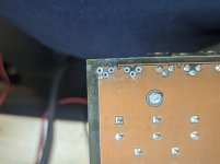
Ok, you should also know I did discover something else on the 'bad' amp. I found a power supply FET completely shorted (Q823), and it's 47 ohm gate resistor was totally fried, so bad that when I tried to desolder the resistor one of it's pads came right off the board. Q823, right at the end of the power supply FET line up. Amazingly, it also had a blown ground trace on the bottom layer - see the attached pic. After I discovered the burnt FET, I removed all of the power supply fets on the bad amp, and I've been testing it that way since. I tested all of the other FETs I removed from the bad amp and Q823 was the only one that wasn't ok.
Anyway, I already knew the main supply on the bad amp wasn't running, because there was no DC on either side of the the speaker output terminals relative to ground, before or after the 15 second turn-on delay. I confirmed that by probing the 3525 outputs. Neither one pulses, but they are very noisy (DC value of 0). I also checked they are not shorted, they read to ground the 2.2k resistors near the bottom on the driver board. The same pulse "noise" also travels through to the 47 ohm gate resistors for the PS FETs, making me think the drive circuits through the transformers are working ok. I was initially assuming the 3525 was bad, or, that is it was a lingering issue with the daughterboard start-up. But, the 3525 appears to be supplied properly after the 15 sec turn on delay (multimeter on the pins). So, I was originally going to swap in a 3525 from a donor 300/4v2 I've got lying around. But, I didn't want to try it until after tracking down the start up delay in case it was contributing. (I also considered it could be the other way around? But I think the fact that it eventually starts the known good amp dispels this option.)
So, to recap: in the bad amp, nothing starts initially (except the green LED), and after 15 seconds the low voltage supplies do come up, and there's a very brief flash of the red and yellow LEDs, but that's it. There's no drive on the output of the 3525. When probed, it looks very noisy, but with no proper pulses. The amp draws a small amount of current when the low voltages come up, about 1A. When I place the same daughter board into my known good amp, same 15 second delay behavior (with green LED), but then everything comes up (low voltage supplies, main supply, and normal iddle current). It also has a brief red and yellow flash at 15 seconds.
I did check the output FETs on the bad amp and they don't measure shorted, and they do get pulses on their gates. So I think the output section on the bad amp is running ok. The rectifiers don't appear shorted either.
I've never seen a combination failure mode like this, maybe one failure contributed to the other? Or one wasn't enough to 'disable' the amp, letting the other failure happen later? Totally weird. But, I'm hoping that since the repaired daughterboard does start up in my known good amp (after the 15 second delay), that the issues can be trouble-shot and repaired separately (but maybe not?)
Anyway, I'm totally open to what you might suggest next.
I just double checked, and you are correct, pin 6 does stay high as long as +12V is connected to B+, I think I must have jostled my probe when I was taking my notes. It makes sense, since pulling that pin low after the 4.7 ohm resistor would sink 3A from B+, not very practical 😉
To answer your questions, when I place the 'repaired' daughter board into my known good amp, nothing in the amp starts until about 15 seconds, including the low voltage supplies. Only the green LED comes on initially. The amp doesn't draw current, but it then starts totally normally after the 15 delay.
When I place the repaired board back into it's original 'bad' amp, similar behavior. Only the green LED comes on initially - nothing else until 15 seconds. Then, the low voltage supplies only come up at that time (but not the main supply- more on that below).
So based on this, I can only conclude (maybe?) that the delay issue is a problem that remains on the repaired daughterboard. The 'good' amp starts as expected when it has it's own daughterboard - 1 to 2 seconds. I've been too chicken to put the known good daughterboard into the bad amp, to see if it can bring up the low voltage supplies in 1-2 seconds - I was nervous enough about putting the repaired daughter board in the good amp! But if you think it would reveal something useful, I'll give it a go.
Ok, you should also know I did discover something else on the 'bad' amp. I found a power supply FET completely shorted (Q823), and it's 47 ohm gate resistor was totally fried, so bad that when I tried to desolder the resistor one of it's pads came right off the board. Q823, right at the end of the power supply FET line up. Amazingly, it also had a blown ground trace on the bottom layer - see the attached pic. After I discovered the burnt FET, I removed all of the power supply fets on the bad amp, and I've been testing it that way since. I tested all of the other FETs I removed from the bad amp and Q823 was the only one that wasn't ok.
Anyway, I already knew the main supply on the bad amp wasn't running, because there was no DC on either side of the the speaker output terminals relative to ground, before or after the 15 second turn-on delay. I confirmed that by probing the 3525 outputs. Neither one pulses, but they are very noisy (DC value of 0). I also checked they are not shorted, they read to ground the 2.2k resistors near the bottom on the driver board. The same pulse "noise" also travels through to the 47 ohm gate resistors for the PS FETs, making me think the drive circuits through the transformers are working ok. I was initially assuming the 3525 was bad, or, that is it was a lingering issue with the daughterboard start-up. But, the 3525 appears to be supplied properly after the 15 sec turn on delay (multimeter on the pins). So, I was originally going to swap in a 3525 from a donor 300/4v2 I've got lying around. But, I didn't want to try it until after tracking down the start up delay in case it was contributing. (I also considered it could be the other way around? But I think the fact that it eventually starts the known good amp dispels this option.)
So, to recap: in the bad amp, nothing starts initially (except the green LED), and after 15 seconds the low voltage supplies do come up, and there's a very brief flash of the red and yellow LEDs, but that's it. There's no drive on the output of the 3525. When probed, it looks very noisy, but with no proper pulses. The amp draws a small amount of current when the low voltages come up, about 1A. When I place the same daughter board into my known good amp, same 15 second delay behavior (with green LED), but then everything comes up (low voltage supplies, main supply, and normal iddle current). It also has a brief red and yellow flash at 15 seconds.
I did check the output FETs on the bad amp and they don't measure shorted, and they do get pulses on their gates. So I think the output section on the bad amp is running ok. The rectifiers don't appear shorted either.
I've never seen a combination failure mode like this, maybe one failure contributed to the other? Or one wasn't enough to 'disable' the amp, letting the other failure happen later? Totally weird. But, I'm hoping that since the repaired daughterboard does start up in my known good amp (after the 15 second delay), that the issues can be trouble-shot and repaired separately (but maybe not?)
Anyway, I'm totally open to what you might suggest next.
Attachments
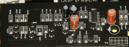
With the bad driver board in the bad amp, when you apply remote voltage do you see 12v switched onto the collector of Q407?
My apologies, I can't locate Q407 - can you direct me to it?
Also, I decided to put the good daughterboard into the bad amp - and the LV supply on the bad amp came up nearly instantly. So the delayed start up is definitely following this board with ground plane damage around.
I noticed two traces going all the way over to the pre-amp side. I just did a quick visual over there, and confirmed connectivity - could the issue be from over there?
Thanks! It's interesting that it's not labelled on either of my boards (rev 2).
On that transistor collector (middle pin & tab) I get 0.5V right after applying remote, and then it slowly creeps to about 0.6V@15 seconds, then it snaps up to 12V. When I remove remote, it immediately collapses to about 0.5V, and slowly drains.
On that transistor collector (middle pin & tab) I get 0.5V right after applying remote, and then it slowly creeps to about 0.6V@15 seconds, then it snaps up to 12V. When I remove remote, it immediately collapses to about 0.5V, and slowly drains.
Ok, I pulled Q407 off the board and it tests as a good pnp. No change after re-soldering it. Grabbed a second (identical one) from my donor amp, and it measures the same way on mt LCR tester. Swapped it in, no change either.
Does pin 14 of the 324 remain high until remote is applied and then drop to near ground for 15 seconds after remote is removed?
No, it doesn't:
- It reads high before remote is applied
- It stays high after remote is applied
- At 15 seconds it drops to near ground (on it's own) with remote still applied. It then stays that way indefinitely, although I do see some minor wriggling every 15 seconds or so, like something is trying to switch it.
- If I then remove remote anytime after it goes low, it instantly goes back high.
Last edited:
On pin 12:
- Before remote: 3.6V
- After applying remote: no change for 15 seconds, then 3.7V
- After removing remote: back to 3.6V
Pin 13:
- Before remote: 0.6V
- After applying remote: it jumps to about 1.5V, then rises steadily like it's charging a capacitor
- At the 15 second mark (when the LV supply kicks on) it's about 4V. It keeps climbing for about another 20 seconds then settles at 5V.
- After removing remote: instantly collapses back to 0.6V
No, I had previously checked it. I measure continuity (I measure 0.1 ohms) from pins 1 and 10 on the header (gnd) through to the two pads on R424 and R428 which are connected through that via.
- Home
- General Interest
- Car Audio
- JL1000/1 - 15 second turn on delay