The outputs survived, correct? If so, I think I'd leave them.
The PS FETs are likely obsolete and unavailable from any reputable distributor. Unless you have a known good sub, you'll have to do a parameter search to find a suitable sub.
Did you install the remaining good PS FETs to confirm that the amp is fully functioning?
The PS FETs are likely obsolete and unavailable from any reputable distributor. Unless you have a known good sub, you'll have to do a parameter search to find a suitable sub.
Did you install the remaining good PS FETs to confirm that the amp is fully functioning?
I installed four of the old FETs back in to the power supply, and confirmed proper sine wave on the output terminals.
And that's great, this board has so much thermal mass, I'd rather just concentrate on the PS Fets haha.
I've also found a candidate replacement for the old ones - IRL4132. Do you have any experience using this FET?
Thanks
And that's great, this board has so much thermal mass, I'd rather just concentrate on the PS Fets haha.
I've also found a candidate replacement for the old ones - IRL4132. Do you have any experience using this FET?
Thanks
Installed 4? One in each of the 4 banks?
When I was working, the originals were still available. The IRF3709 replaced the originals. Compare it to the following, The drive circuit can probably handle the ones you listed but the Qg and Ciss are higher than the originals.
https://www.mouser.com/datasheet/2/196/Infineon_IRLB8748_DataSheet_v01_01_EN-3166547.pdf
Last edited:
The IRL8748 looks like it'll be a good match, thank you. It's only a few cents more than IRL4132 I was looking at, but has better all-around current ratings. It's Ciss and gate charge are less than the 60N03L's that were in this amp, so I think I'm going to try them.
I did briefly power the amp up with a pair of old transistors in each bank (I meant to say 4 pairs in my post above). After seeing a nice offset sinusoid in each output side I put in the rest of the good 60N03L FETs. I confirmed I can get about 68Vrms AC on the output (measured differentially like a speaker) before clipping sets in. DC offset of each side of the output is 58VDC. DC offset differentially is about 50mV, but I know I can trim it with the labelled potentiometer on the board.
Would you recommend changing all of the existing 47 ohm gate resistors? I see this advice posted sometimes when changing out PS FETs.
In the amps that used the 3709 FETs, they used 22 ohm gate resistors. I don't think it really matters with the transformer drive but you may want to go to a 22 ohm if you're going to replace the gate resistors.
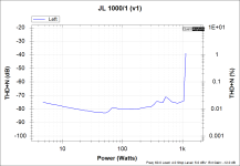
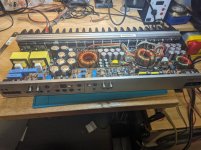
Hi, I wanted to let you know, the amp is mounted back to the heatsink, and working great! Attached is a THD+N graph. I ended up using 47 ohm gates with the IRL8748 in the PS. I also found two more shorted npn and u800 failed during initial stress testing. The section in your tutorial about transistor testing really helped me troubleshoot that.
I have an extra question for you - would you consider these rail caps 'bulged'? I'm going to pull the board out one more time (I'm going to use a jig to clamp the end-caps on to support the board, like in your tutorial) to put zip ties on the output inductors, and wondering if I should do the caps while it's out.
Cheers
Attachments
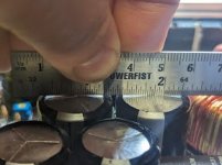
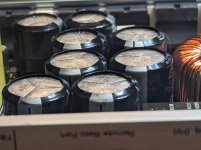
The two with the rule do look bulged but I can't see it in the other photo.
The caps are up to you. If they didn't lose any electrolyte and didn't vent, they are likely still within tolerance. You can check that.
The caps are up to you. If they didn't lose any electrolyte and didn't vent, they are likely still within tolerance. You can check that.
- Home
- General Interest
- Car Audio
- JL1000/1 - 15 second turn on delay