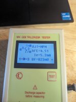
Please stop using a 'tester' to check transistors and use a multimeter.
That transistor has no internal diode.
If the copper is there and those resistors connect to ground, there is no reason to do anything there.
That transistor has no internal diode.
If the copper is there and those resistors connect to ground, there is no reason to do anything there.
Ok - I did not know a tester wouldn't be reliable for this.
For that transistor, with my multimeter in diode check, positive lead to negative lead:
For that transistor, with my multimeter in diode check, positive lead to negative lead:
- Base to emitter: 0.63V
- Base to collector: 0.7V
- Emitter to base: O/L
- Collector to base: O/L
- Collector to emitter: O/L
- Emitter to Collector: 0.7V <--- this should be O/L, right?
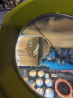
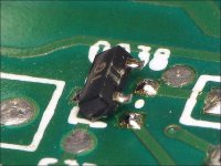
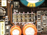
It should be open. If you are ever uncertain, lift (as shown below) another transistor with the same markings and check it or compare to a new one if you have one in stock.
Those testers have caused me more problems trying to help others than you would believe.
Those testers have caused me more problems trying to help others than you would believe.
Attachments
That's great to know - and thank you for the pic - way easier than trying to probe them completely off the board!
So, it turns this transistor is the issue. I popped a 1Bt on to the board from my donor amp, and now there's no more 15 second turn on delay. The LV supply comes up instantly when remote is applied, and then persists or stays up for about 15 seconds after remote is removed (which I think is the correct behavior - if not please let me know).
So, thank you! I really appreciate the help. I'm going to try replacing the 3525 this evening I think, and see if I can get some gate drive, and get this thing back up and running.
Why are you replacing the 3525?
Yes and the 15 seconds gives you time to check drive on the output transistors without the rail voltage.
Yes and the 15 seconds gives you time to check drive on the output transistors without the rail voltage.
I'm not sure if I'll replace it yet. I get no PWM drive for the power supply FETs, and probing the outputs of the 3525 I see no pulses. I have a 3525 on the donor to try if I need. I'm going to check the voltages on all of the 3525 pins on my known good amp and compare them to this one first though. Could be the inverting, NI, or compensation inputs aren't correct. Do you know if there's a common failure point on these PS supply
driver boards?
driver boards?
Those boards are generally not a problem.
Compare the voltages on the 10 pin connectors between the amps to make sure that the rail supply is being told to switch on.
Compare the voltages on the 10 pin connectors between the amps to make sure that the rail supply is being told to switch on.
Here's what I found:
On the 10 pin connector, all voltages are the same between the two amps except for:
Similarly, besides the outputs of the 3525, I only get differences on:
So I think you may be right, something seems not right with the soft start, and the compensation pin may just be pulling low as a result.
Are pins 7 & 8 on the 10-pin header related?
On the 10 pin connector, all voltages are the same between the two amps except for:
- Pin 7: reads 0.63V on the known good amp, 0.018V on the bad amp
- Pin 8: reads 0.42V on the known good amp, 0.013V on the bad amp
Similarly, besides the outputs of the 3525, I only get differences on:
- Pin 8 (soft start): 1.8V on the known good amp, 4.47V on the bad amp
- Pin 16 (comp): 5.56V on the known good amp, 0.57V on the bad amp
So I think you may be right, something seems not right with the soft start, and the compensation pin may just be pulling low as a result.
Are pins 7 & 8 on the 10-pin header related?
Did you get the tutorial downloaded? The JL1000 page has information on the various pins. I'll try to fill in on what you need here.
Are you sure that you have the SS vs the good/bad amp right?
Pins 7 and 8 of the 10 pin connectors are not related. One is for the low-voltage supply and the other is for the SS of the rail supply.
Are you sure that you have the SS vs the good/bad amp right?
Pins 7 and 8 of the 10 pin connectors are not related. One is for the low-voltage supply and the other is for the SS of the rail supply.
I just checked and the tutorial is done downloading, but I haven't looked at it yet. I'll definitely dig into it after a good sleep.
So I re-checked pins 7 & 8, and did learn that the remaining issue is now following the bad amp (and not the daughter board) around:
I also saw that pin 7 is directly connected to the input of a LM311- good place to go next?
I'll definitely check out the tutorial
So I re-checked pins 7 & 8, and did learn that the remaining issue is now following the bad amp (and not the daughter board) around:
- The bad amp (with either daughter board): pin 7 is 0.018V and does not stay high after remote is removed
- The good amp (with either daughter board): pin 7 is 0.64, and stays high for 15 secs after remote is removed
- Pin 8 shows the same behavior (Good amp, any daughter board: 0.04V with remote on, 0.7V for 15 secs after remote is removed. Bad amp with any daughterboard: 0.013V, and it does not stay high after remote is removed).
I also saw that pin 7 is directly connected to the input of a LM311- good place to go next?
I'll definitely check out the tutorial
1: "The bad amp (with either daughter board): pin 7 is 0.018V and does not stay high after remote is removed"
^^^ So it's never high, correct?
2: "The good amp (with either daughter board): pin 7 is 0.64, and stays high for 15 secs after remote is removed"
^^^ High as in 0.64v?
Are you referring to the pins on the 10 pin connector as numbered below?
Are you referring to the LM311 on the PS driver board (U702)? If not, which one?
Attachments
Hi, my answers in [brackets] below:
1: "The bad amp (with either daughter board): pin 7 is 0.018V and does not stay high after remote is removed"
^^^ So it's never high, correct? [Correct]
2: "The good amp (with either daughter board): pin 7 is 0.64, and stays high for 15 secs after remote is removed"
^^^ High as in 0.64v? [Correct]
Are you referring to the pins on the 10 pin connector as numbered below? [Yes]
Are you referring to the LM311 on the PS driver board (U702)? If not, which one? [Yes, U702]
To connect to the LM311, pin 7 would have to connect to one pin of the PS board header pins. Which one connects to pin 7 of the 10 pin connector?
Ok, so I traced pin 7 through to pins 1 and 4 on the LM311, which are... gnd and VEE. It turns out when the daughter board is mounted in the amp, pin 7 becomes connected to ground (which is why I thought I found a direct connection). Which makes sense, considering the voltages I read on pin 7 for the bad amp with either daughter board installed (18mV).
So, forget the LM311 for now... I'm going to try and follow pin 7 on the known good amp with my multimeter in beep mode and see what devices it connects to on the main amp board.
Btw, I'm loving the tutorial so far. It's a really fantastic resource!
So, forget the LM311 for now... I'm going to try and follow pin 7 on the known good amp with my multimeter in beep mode and see what devices it connects to on the main amp board.
Btw, I'm loving the tutorial so far. It's a really fantastic resource!
Hey, I've got great news! I've got good pwm drive on the SG3525 through to the gates at the supply FETs. So this amp will live again.
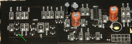
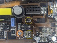
I found two issues in the circuits near the 10 pin header on the amp board. The ZC in the pic, was shorted base-emitter. The emitter of this npn was connected to ground through the via.
I also found the 10k resistor (see the pic) was reading open - it's a pull-up resistor I think, also connected to pin 7 on one side and LV supply on the other.
Anyway, I'm going to get to work ordering new FETs, get this guy up and going. Since the amp is apart, I'm thinking it would be good preventative maintenance to change the outputs as well? Is there anything you recommend for either the power supply FETs and output FETs? I think I saw IRF3205 for the PS were recommended, but I can't remember where just now.
Attachments
For the tutorial, be sure to carefully read the yellow section on the Repair Introduction page. It will make navigating the tutorial so much more efficient.
Did you find the JL 500 and 1000 pages? It's mainly general information but may be helpful.
What are the original part numbers for the FETs in this amp? I think the PS uses logic level, low-voltage FETs. This is a rev 2 which I've never seen.
Did you find the JL 500 and 1000 pages? It's mainly general information but may be helpful.
What are the original part numbers for the FETs in this amp? I think the PS uses logic level, low-voltage FETs. This is a rev 2 which I've never seen.
Hi, yes I had a chance to read through both today - you've created some really valuable reference information for these amps!
- For the amp you've been helping me with, the amp board is a Rev2, and the PS FETs are 60N03L with 47 ohm gate resistors. The output FETs are 45N20B with 4.7 ohm gate resistors (4R7).
- The other amp I have (that I've been referring to as the 'known good amp') amp's board is Rev5, and it has IRF3707 FETs in the PS and 45N20B FETs in the output. Same gate resistances as the other.
- Home
- General Interest
- Car Audio
- JL1000/1 - 15 second turn on delay