What's up friends? I have this amplifier with failure in both stages, it is my first jl to be repaired and I would like to know if you can tell me the part number of the driver transistors of the PS, the driver ic of the output stage and if it is that I can place it in the output irf540n? greetings and thank you very much.
Attachments

For the outputs, I've never tried the N version. The originals are available from Newark's US warehouse and in Europe.
https://www.newark.com/vishay/irf540pbf/n-channel-mosfet-100v-28a-to-220ab/dp/63J7322?CMP=AFC-OP
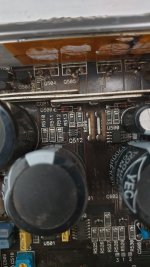
The MIC4427 is the low-side driver for the outputs. The small transistors on either side of the outputs are for the high-side drive.
The PS drivers are Q608-Q611.
Carefully check all resistors between the drivers and the FETs for both the output stage and the PS.
https://www.newark.com/vishay/irf540pbf/n-channel-mosfet-100v-28a-to-220ab/dp/63J7322?CMP=AFC-OP
The MIC4427 is the low-side driver for the outputs. The small transistors on either side of the outputs are for the high-side drive.
The PS drivers are Q608-Q611.
Carefully check all resistors between the drivers and the FETs for both the output stage and the PS.
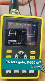
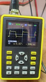
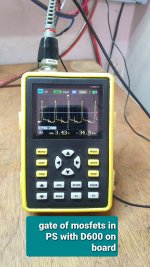
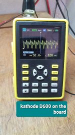
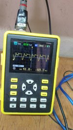
What's up friend I'm back... I just put together the PS part and you can hear the pwm ic vibrate, it only does it if it has the d600 rectifier inside, what else could I check? also in the output stage i changed resistors of 100 ohms, 10 ohms and 47 ohms i still haven't assembled the irf540. In the mic4427 I have pulses on pins 5 and 7 it is from the ic only on the pads where the fets go I can't see them
that's right, the ic was struggling but checking further i discovered several damaged transistors ktc3207, kta1070 and 2n3906, i go to the store to buy them, the noise has disappeared but i still see the wrong square wave when i put the d600 on the board, I will replace the transistors and see their behavior
Wrong square wave?
What you probably see is the square wave that's produced by a regulated power supply when the duty cycle is reduced because the target rail voltage has been reached.
What you probably see is the square wave that's produced by a regulated power supply when the duty cycle is reduced because the target rail voltage has been reached.

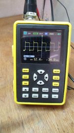
Reduce the 12v supply voltage as low as the amp will stay on and look at the waveforms.
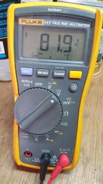
Measure the rail voltage through the full range of the 12v supply voltage. It's likely precisely the same (about 81v).
Measure the rail voltage through the full range of the 12v supply voltage. It's likely precisely the same (about 81v).
Excuse me, I have doubts about the driver transistors for PS fets... Could you tell me where each one goes since the device came from another workshop and it seems to me that the error is there
Emitter follower pairs.
The collector of the PNP transistor is connected to ground.
The 2020 rectifier isn't a suitable sub. What happened to the original rectifier?
The collector of the PNP transistor is connected to ground.
The 2020 rectifier isn't a suitable sub. What happened to the original rectifier?
Reduce the 12v supply voltage as low as the amp will stay on and look at the waveforms.
Measure the rail voltage through the full range of the 12v supply voltage. It's likely precisely the same (about 81v).
Attachments
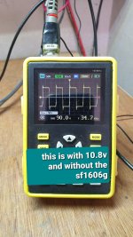
The waveforms require the rectifier in the circuit. The pulse width will be at max without the rectifier.
- Home
- General Interest
- Car Audio
- JL Audio Slash 500.1 help