There are three LM319 in this amp. Two on the power supply and one on the vertical driver board. I once again have the amp on the bench, connected to a 2ohm dummy load and fed a 50hz test tone.
The LM319 which is closest to the UC3525ADW may be the one involved in this issue. I am not fully verse in the operation of the LM319 so I will just report my findings and hopefully it will make enough sense to be of help. I am hoping to understand what happens on the bench so I know what to look for in the car.
Both LM319 in the power supply section seem to only be using IN/OUT1.
The LM319 that is next to the NE555 has +4.8v on VCC, IN+ and IN- both have +2.2v, and OUT1 has 2.6v. None of these voltages change during the whole range of no load/signal, all the way up to shutdown.
The LM319M closest to the UC3525 has different voltages. VCC is +10v at idle and the amp shuts down/restarts when it goes below 8v. IN+ has 2.3v, IN- has +3.1v at idle down to +2.4v before restart, OUT1 has 0.2v at idle and at full output before restart there is no voltage reading but touching Pin12 shuts down the amp. Touching the probe to IN+ shuts down the amp and holding the probe to Pin4 causes the protection light to flicker exactly the same way it did before. VCC is connected directly to leg2 of a 2SC3200 and OUT1 is connected to leg3.
Is the amp shutting down because of the LM319 VCC voltage dropping below 8v, or because IN- drops to below 2.5v, or neither one of these?
Could the problem be something causing clipping in the output section, or one or more of the outputs themselves?
I removed the 2SC3200 that the LM319 OUT1 is connected to leg3, and I monitored the voltage on the hole for leg2 which is connected to VCC of the LM319. I assume that this transistor is responsible for shutting down the amp when a fault is detected. The voltage never dropped below 10.5v but there was a pop sound that occurred at about the same level of output that the amp would shut down, but the amp remained on since the protection was disabled. I am wondering bif this sound is clipping from the output section?
Since the protection is supposedly working as it should and none of the supply voltages are dropping, I assume that the protection is kicking in due to a fault in the output section. The only similar experience I had was with a USAmps MD2D that was going into protection as the volume was turned up and changing outputs solved the problem. I am just checking to see if there is anything else worth checking before pulling out and replacing eight possibly good outputs. I would like to do as little additional damage as possible..
I have IRF3710Z on hand if those would work, and if any other changes would be necessary.
Why would clipping be a problem?
I've tried using other FETs as outputs and without much success. Even if they were rated for higher current, they didn't seem to be more reliable. I'd use the original parts.
I've tried using other FETs as outputs and without much success. Even if they were rated for higher current, they didn't seem to be more reliable. I'd use the original parts.
What would that pop noise be that I heard through the subwoofer? It was the same noise the amp makes when it shuts down with protection, but this time the protection was disabled so the amp didn't shut down. I just assumed that the audio wave turned to DC voltage. I may have incorrectly referred to it as clipping. What I am wondering is if one or more outputs are sending out DC voltage at high output. I wasn't hoping to improve reliability, I was just thinking that one or more outputs might be damaged.
If changing the outputs is unlikely to make a difference, what do I do next? I do not have the original FETs.
If changing the outputs is unlikely to make a difference, what do I do next? I do not have the original FETs.
Last edited:
Does the amp malfunction when driven into hard clipping with no load?
I've never heard of having outputs that would cause this sort of problem but work perfectly most of the time.
I've never heard of having outputs that would cause this sort of problem but work perfectly most of the time.
Well, I had never tested it without a load so I just did after your last post. When I first powered up the amp feeding it a 50hz tone and monitoring the output terminal with the scope, at hard clipping, there was a ticking/clicking sound coming from either the PS transformer, the Low Voltage transformer, the 2 vertical inductors(?), or the white block resistors. I touched all of them trying to identify the source of the noise, but I turned the amp off and went to get my stethoscope to track the sound, and voltmeter to monitor voltages. After setting everything up and turning on the amp, it no longer made the clicking sound when the audio output was at hard clipping. The amp does not shut down when the output clips without a load. I reattached the 2ohmnload and tested again and the protection kicked in as normal when the + power terminal reads close to 10v and the LM319 VCC reads close to 8v.
I think the sound was possibly coming from the PS transformer as I twisted it a bit prior to going for the stethoscope. Is this a meaningless finding and not likely related to the issue, or could the transformer clicking shut down the amp when driven hard?
I think the sound was possibly coming from the PS transformer as I twisted it a bit prior to going for the stethoscope. Is this a meaningless finding and not likely related to the issue, or could the transformer clicking shut down the amp when driven hard?
So whatever is happening is causing the transformer(or some other component on the board} to buzz as it occurs. I removed the 2SC3200 transistor responsible for shutting down the amp so I can capture what is happening on a scopeshot. I did the same thing in the vehicle and all that was heard in the subwoofer was a scratching/scraping type sound every time a heavy bass note hit, but the bass continued playing the lighter notes uninterrupted.
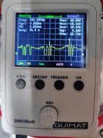
These scopeshots are inside on the bench with a 50hz test tone, with the protection transistor removed, with a 2ohm dummy load connected. The sine wave is clean right up to the point when the amp starts buzzing and the noise shows up on the scope. Maybe seeing what is occurring may help with offering a possible cause. This occurs way before there is any clipping of the output signal.
These scopeshots are inside on the bench with a 50hz test tone, with the protection transistor removed, with a 2ohm dummy load connected. The sine wave is clean right up to the point when the amp starts buzzing and the noise shows up on the scope. Maybe seeing what is occurring may help with offering a possible cause. This occurs way before there is any clipping of the output signal.
Attachments
Did you check the outputs of the LM319 on the driver board to see if they corresponded to the pulses you have in the output here?
The noise does correspond to the activity seen on the LM319.
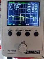
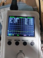
shot1 is pin4 when the noise occurs
shot2 is pin12 just before the noise starts
shot3 is pin12 when the noise occurs
what could be causing the trigger on pin4? do i need to trace pin4 back to its source?
I just read your last post. I didn't check the LM319 on the driver board.
shot1 is pin4 when the noise occurs
shot2 is pin12 just before the noise starts
shot3 is pin12 when the noise occurs
what could be causing the trigger on pin4? do i need to trace pin4 back to its source?
I just read your last post. I didn't check the LM319 on the driver board.
Attachments
Last edited:
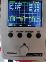
tested the LM319m on the driver board. it prematurely triggers the noise when the scope touches the pins, but turn the gain knob a bit more and the amp makes the noise.
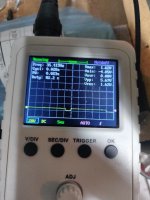
pic1 is pin4 when the noise is audible
pic2 is pin12 when the noise is audible
pic1 is pin4 when the noise is audible
pic2 is pin12 when the noise is audible
Attachments

Why are you using this scope if you have the owon?
Is this IC being powered by a split supply or by a single-ended supply?
Is this IC being powered by a split supply or by a single-ended supply?
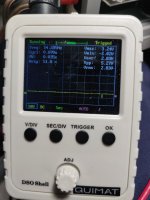
Both inputs are being used on this IC. I will post the voltage readings on all the pins. I am still figuring out ICs but how come pin12 has 5v on it when the +/-inputs are both less than 1v? Or is that 5v originating from somewhere else? Is that 5v the low voltage supply? So when pin12 of this LM319 has an output, it is interfering with the 5v power supply to the various ICs which triggers the protection, and also causes the buzzing, like a feedback? Just trying to figure out what I don't understand...
LM319M on driver board
1) 0
2) 0
3) 0
4) 0.98
5) 0.14
6) -15.05
7) 12.28
8) 0
9) 9.15
10) 0.40
11) 15.76
12) 5.03
13) 0
14) 0
The DSO was just easier to use right now. If the OWON will make the job easier or quicker, I will use that one.
LM319M on driver board
1) 0
2) 0
3) 0
4) 0.98
5) 0.14
6) -15.05
7) 12.28
8) 0
9) 9.15
10) 0.40
11) 15.76
12) 5.03
13) 0
14) 0
The DSO was just easier to use right now. If the OWON will make the job easier or quicker, I will use that one.
Last edited:
The pot near the IC is likely the threshold. I think the 2-pin headers is likely the test point. Measure the voltage across it very carefully at idle and record the value. If you want to see if the pot makes a difference, you can try adjusting it.
Is there a transistor at the output of the 319 like for the low-voltage section?
Is there a transistor at the output of the 319 like for the low-voltage section?
Adjusting the pot did not change the point when the noise started to come in. At idle, I got a reading of 0.31 and I adjusted it down to 0.15, and up to 0.50 with no perceptible change on the bench. Don't know if it would make a difference in the car with music playing.
Pin12 of the LM319 goes directly to pin10 (B3) of an AHC132 on the driver board.
Pin12 of the LM319 goes directly to pin10 (B3) of an AHC132 on the driver board.
What is the purpose of the LM319 on the driver board?
What could be triggering Pin4 on the LM319, or is this IC responding to a wider occurrence in the amp, and LM319 is not responsible for the noise/protection trigger?
What could be triggering Pin4 on the LM319, or is this IC responding to a wider occurrence in the amp, and LM319 is not responsible for the noise/protection trigger?
- Home
- General Interest
- Car Audio
- JL Audio E1800DM