A couple of general notes.
For the amps I've tested this on (not a rev11 but a 3 and 10), the 10 pin connector is all you need for the jumpers when testing only for drive signals. You can leave the others connected but if they pull loose, you can leave them out.
The 4.83v on the supply pin of the LM319 is OK. The voltage is dropping across a 10 ohm resistor that they use to improve filtering.
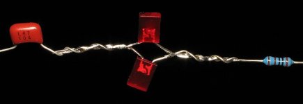
The LED device (attached) won't be as useful as I'd hoped so, since you'd have to order the parts, I won't recommend that you make one.
Remove the main rectifier (D600 on the heatsink). With that out, you can leave the remote voltage applied.
If you're not 100% sure that the remaining output FETs are OK, remove them.
Check all driver transistors and resistors in the area of the output FETs.
Using the DC offset trimmer potentiometer on the board, measure the DC voltage across each of the output FETs again (Vgs, voltage gate to source) three different times.
1. as the pot is now
2. pot fully clockwise
3. pot fully counterclockwise
Copy and paste the following and fill in. Post exact reading on the meter (all digits to the right of the decimal).
pot position?
Q504
Vgs:
Q505
Vgs:
Q506
Vgs:
Q507
Vgs:
For the amps I've tested this on (not a rev11 but a 3 and 10), the 10 pin connector is all you need for the jumpers when testing only for drive signals. You can leave the others connected but if they pull loose, you can leave them out.
The 4.83v on the supply pin of the LM319 is OK. The voltage is dropping across a 10 ohm resistor that they use to improve filtering.
The LED device (attached) won't be as useful as I'd hoped so, since you'd have to order the parts, I won't recommend that you make one.
Remove the main rectifier (D600 on the heatsink). With that out, you can leave the remote voltage applied.
If you're not 100% sure that the remaining output FETs are OK, remove them.
Check all driver transistors and resistors in the area of the output FETs.
> Does the other meter you have read frequency, duty cycle?
Using the DC offset trimmer potentiometer on the board, measure the DC voltage across each of the output FETs again (Vgs, voltage gate to source) three different times.
1. as the pot is now
2. pot fully clockwise
3. pot fully counterclockwise
Copy and paste the following and fill in. Post exact reading on the meter (all digits to the right of the decimal).
pot position?
Q504
Vgs:
Q505
Vgs:
Q506
Vgs:
Q507
Vgs: