I don’t actually know what the RIPS system is but I thought it was the system within the amp that makes it so it produces rated power regardless of voltage and speaker impedance?
How can I tell if low voltage mode is in effect? I’m setting this amp up on bench now and going to try it and see if I can see a difference that would indicate it
How can I tell if low voltage mode is in effect? I’m setting this amp up on bench now and going to try it and see if I can see a difference that would indicate it
RIPS, I never know if it's a term made up or something real. After a search... R.I.P.S. is the system that they use to either regulate voltage or to reduce the maximum drive to adjust for various impedances.
There is a transistor standing near the low-voltage transformer, Do you see a square wave on it's drain (tab) when you connect remote?
As a side note, you don't need to pulse the remote when all of the FETs are out of the circuit. Pulsing is to prevent the main/rail supply from powering up.
There is a transistor standing near the low-voltage transformer, Do you see a square wave on it's drain (tab) when you connect remote?
As a side note, you don't need to pulse the remote when all of the FETs are out of the circuit. Pulsing is to prevent the main/rail supply from powering up.
Last edited:
G’morning, I got in a shipping damaged amp the other day, been dealing with that ever since ...fun, lol.
And ya the R.I.P.S system was one of the 1st I think to employ that type of “power regardless of impedance” or was it Alpine’s PDX amps? I forgot, pretty cool nonetheless 🙂
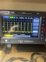
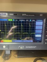
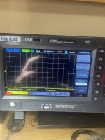
As far as the square wave on Drain (middle tab) it’s about as ugly a square wave as I’ve ever seen one ...I don’t think it even counts as a square wave ...lol, I did get a “decent” one on the Gate tho (first tab) I’ve included pics of each, Gate, Drain, Source, Source just looks like voltage and no wave, I didn’t adjust scope tho after reading Gate, also the location of that transistor you’re referring to.
And ya the R.I.P.S system was one of the 1st I think to employ that type of “power regardless of impedance” or was it Alpine’s PDX amps? I forgot, pretty cool nonetheless 🙂
As far as the square wave on Drain (middle tab) it’s about as ugly a square wave as I’ve ever seen one ...I don’t think it even counts as a square wave ...lol, I did get a “decent” one on the Gate tho (first tab) I’ve included pics of each, Gate, Drain, Source, Source just looks like voltage and no wave, I didn’t adjust scope tho after reading Gate, also the location of that transistor you’re referring to.
Attachments
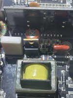
The tab consists of the metal back including the extended section with the mounting hole. The parts soldered into the board are terminals/legs.
http://www.interfacebus.com/semiconductor-transistor-packages-TO-220.html
The waveforms are as expected.
When the low-voltage supply is operating as shown in the photos, you should have supply voltages to the op-amps and to the drive circuit for the output transistors.
You didn't adjust the scope, it's set to auto. Learn to set the timebase and vertical amplifier manually.

Ahh ok, that makes sense, I’ve seen some probe on that Tab in some videos, ty and ty for link, saving it and going to go over it til it’s stuck in my head lol 🤓
Ya I’m def still learning my waves, I’m realizing recently they arent always just point blank perfect wave like the calibration wave in the corner of scopes, and that they can “grow” to a proper wave while building rail voltage, I remember something like that during some repair videos I was watching.
And ya I do rely on Auto-Set too much, it’s almost a liability too cuz I have to hold my probe on point of contact without slipping while I reach over to press Auto-Set button, taking my eyes off the probed area ...I’ve slipped a few times 😓
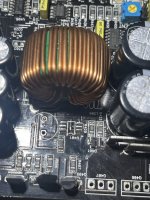
O ya that area that fizzled near the middle Rectifier bottom pad was burnt/carbonized a little. I used a needle probe to gently “dig” out all the carbonized board and checked between pads with DMM for continuity and all looks good now, no idea how or why that happened but thinking it was making a connection somehow 🤷🏼
I’m thinking since drive wave looks good on power supply area I can solder in power supply FETs and Rectifier to test output drive? All gate resistors, etc checked good on DMM along with the other diodes and BJTs.
Ya I’m def still learning my waves, I’m realizing recently they arent always just point blank perfect wave like the calibration wave in the corner of scopes, and that they can “grow” to a proper wave while building rail voltage, I remember something like that during some repair videos I was watching.
And ya I do rely on Auto-Set too much, it’s almost a liability too cuz I have to hold my probe on point of contact without slipping while I reach over to press Auto-Set button, taking my eyes off the probed area ...I’ve slipped a few times 😓
O ya that area that fizzled near the middle Rectifier bottom pad was burnt/carbonized a little. I used a needle probe to gently “dig” out all the carbonized board and checked between pads with DMM for continuity and all looks good now, no idea how or why that happened but thinking it was making a connection somehow 🤷🏼
I’m thinking since drive wave looks good on power supply area I can solder in power supply FETs and Rectifier to test output drive? All gate resistors, etc checked good on DMM along with the other diodes and BJTs.
Attachments
If you didn't get back to white fiberglass, you probably didn't go far enough.
For the most part, you only need 2 or 3 timebase settings. 2ms for audio. 10us for most power supply waveforms and 5us for the class D carrier waves.
Sine, triangle and sawtooth waveforms are relatively well defined but there are exceptions. For an example, a 'modified sine wave' from an inverter is actually a type of square wave. Square waves are not always well defined. Generally if the waveform has fast rise and fall times that are essentially vertical lines, it's considered a square wave.
Gold info ty 🙂 noting that on an index card and posting near Scope!
And ya I don’t think I did go far enough, would a small amount of classic JB Weld be a good filler? I’d like to eventually get into board/trace repair when the time comes and plan on getting various fiberglass, etc to do it but til then I’m thinking JBWeld will be ok, I don’t think it’s conductive but I’ll check.
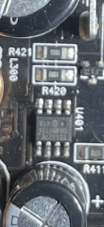
also i went probing around output side before soldering anything in and only one pad has a square wave on Gate of FET Q406, looks to be the 2 inner FETs are the High side bank and the 2 outer FETs the low side, Gate voltages between Q405 & Q406 are different and thinking that’s why the other doesn’t have a sqaure wave? Q406 Gate @ 7.5vPkPk yet Q405 Gate @ 2vPkPk. No other square waves throughout output side.
Does high side give signal to low side? do you need to have power supply FETs & Rectifier installed for Output to show SquareWaves? I thought you did but assuming not after seeing this. Still learning my circuit/signal path/power path 🥴
Also i was probing LM319M @ U406 and the only pin that looks active “to a layman” is pin 12 w/Sqaure Wave @ 6vPkPk.
out of all the Resistors and BJTs near output side only 1 set show a signal, R410 has a square wave on one side and Q411 Base and Emitter each show a Square Wave.
Im going to measure all the resistors near output side and see if anything is off to find out why only one FET is getting a square wave/different voltage which I’m assuming is because of the same problem
And ya I don’t think I did go far enough, would a small amount of classic JB Weld be a good filler? I’d like to eventually get into board/trace repair when the time comes and plan on getting various fiberglass, etc to do it but til then I’m thinking JBWeld will be ok, I don’t think it’s conductive but I’ll check.
also i went probing around output side before soldering anything in and only one pad has a square wave on Gate of FET Q406, looks to be the 2 inner FETs are the High side bank and the 2 outer FETs the low side, Gate voltages between Q405 & Q406 are different and thinking that’s why the other doesn’t have a sqaure wave? Q406 Gate @ 7.5vPkPk yet Q405 Gate @ 2vPkPk. No other square waves throughout output side.
Does high side give signal to low side? do you need to have power supply FETs & Rectifier installed for Output to show SquareWaves? I thought you did but assuming not after seeing this. Still learning my circuit/signal path/power path 🥴
Also i was probing LM319M @ U406 and the only pin that looks active “to a layman” is pin 12 w/Sqaure Wave @ 6vPkPk.
out of all the Resistors and BJTs near output side only 1 set show a signal, R410 has a square wave on one side and Q411 Base and Emitter each show a Square Wave.
Im going to measure all the resistors near output side and see if anything is off to find out why only one FET is getting a square wave/different voltage which I’m assuming is because of the same problem
No fill needed.
Confirm that you have a triangle waveform on pin 5 of the LM319 (near the 555 timer).
Do you have a square wave on the connected (one is unused) legs of D403 and D404?
Confirm that you have a triangle waveform on pin 5 of the LM319 (near the 555 timer).
Do you have a square wave on the connected (one is unused) legs of D403 and D404?
Ok, I’ll save that first “board fill” for when it’s needed lol 🙂
Triangle wave @ Pin5: Yes
Square wave @ D403 & D404: Yes x2
Triangle wave @ Pin5: Yes
Square wave @ D403 & D404: Yes x2
Do you have a square wave on both of the inputs and both of the outputs of the MIC4427 driver IC?
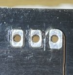
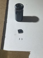
So ...I screwed up, tried removing without a hot air smd rework gun ...****** up 2 pads ...already ordered the SMD rework station along with new TC4427 chips (extra jic) ...how catastrophic is this? I still have the pads but whoopdeedoo 🙁 removed cap to get to the IC FYI.
I’m going to see if I can find any traces underneath but I don’t see any on top of board like the other pads ...figures :/ I can’t believe I thought I could get it off damage free ...first and last time learning this the hard way, so bummed out right now :/
Never cut corners ...ever
I’m going to see if I can find any traces underneath but I don’t see any on top of board like the other pads ...figures :/ I can’t believe I thought I could get it off damage free ...first and last time learning this the hard way, so bummed out right now :/
Never cut corners ...ever
Attachments
I found hot air useless except for adding heat to large pieces like terminal blocks. You can do virtually everything with a good soldering iron. Sometimes ChipQuik helps.
The pads lifted because you applied too much heat. Likely on the pads too long.
Look at the datasheet. Pads 1 and 8 are not used.
The pads lifted because you applied too much heat. Likely on the pads too long.
Look at the datasheet. Pads 1 and 8 are not used.
O wow ok, ya I was using my T12 broad head/chisel tip, I should have used my pencil point. I’m getting pretty good when soldering tiny areas 1 at a time, it’s the multi point areas that get me, also my heat time obviously needs work, more heat less time vs less heat more time usually preferred? Always worried about heat killing components 🥵
Can I ask how you go about multi leg pieces? I just ordered desolder wick as well, do you remove the solder completely before removing the piece or remove the piece while solder is molten like the hot air technique is supposed to work? Im a little concerned about the hot air bleeding onto the components nearby but I’m assuming hotter air faster is better then not as hot applied longer as with the iron?
I’m going to go over your site again to see if there’s soldering iron techniques for multi leg MICs, I think I may get a junk board and practice some. Also I was thinking maybe those legs weren’t used cuz I couldn’t find any traces, that and I just learned not all pins are used on pieces, I found that out when told me both legs not used on D403&D404, I always thought that if it was soldered in, it was in circuit, lol 😅
Thank you so much Perry for everything, I just loaded up on morning coffee so I’m rambling, lol, I’ll report back when I get the chips TC4427 installed, ty! 🖖🏼
There are some boards like those in some of the in the old Lanzar amps that are garbage and virtually impossible to work on without damaging them. The JL boards are good quality but the pads with no connecting traces can't bleed off heat so unconnected pads are more likely than other traces to lift. That said, if you're careful, the pads won't lift.
ChipQuik is the safest option but requires more work and adds cost.
For most ICs, there are a couple (at least) ways to desolder the ICs.
You can apply a lot of new solder to one side and lift that side (from the end with a small screwdriver) and hold while the solder freezes. Then desolder the lifted terminals with braid (or a desoldering pump). You when apply a lot of solder to the other row of terminals and slide the IC off the pads while the solder is molten.
You can also do the second step of the above process for both rows. The excess solder adds thermal mass so the solder remains molten long enough for you to slide the IC off of the pads before the solder freezes.
You need to practice to know what works best for you. You also need to remember that the board can withstand a lot of heat for a short time or less heat for a longer time but a lot of heat for a long time will damage the best boards. I tend to use high heat. For many ICs, it takes less than 5 seconds total to remove a 16 pin IC.
Wow ok, ya 1 leg at a time def wasn’t working, I’m going to practice on a crap blown Pyle board ...seems the perfect candidate lol. I’m also going to look into QuickChip, never heard of it but with “quick” in the name it sounds like a damn good product 😅 lol.
Thank you for the pointers and advice Perry, def helps a lot, I’m sure each board has its own likes and dislikes too, kinda like you were saying between crap and quality, like anything tho I just need to find my technique, etc by practicing. 🖖🏼 Ty bro
Thank you for the pointers and advice Perry, def helps a lot, I’m sure each board has its own likes and dislikes too, kinda like you were saying between crap and quality, like anything tho I just need to find my technique, etc by practicing. 🖖🏼 Ty bro
- Home
- General Interest
- Car Audio
- JL Audio 250/1v2 idle current cycling maxing out PS every 3 seconds, video included.