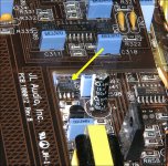
I think something is wrong with 1 of the boards that sits in front of the outputs .
When it’s install I bet 98 volts on all 3 legs of the outputs Q500,501,ect when removed the voltage is normal
When it’s install I bet 98 volts on all 3 legs of the outputs Q500,501,ect when removed the voltage is normal
The vertical boards drive the high-side FETs. The FETs you listed are the low-side FETs and are driven by the 4420s on the main board.
I still have an isssue I have full rail voltage measured directly across the outputs
not sure where the voltage is coming from
not sure where the voltage is coming from
I removed the outputs and the dc voltage is gone across the speaker terminals .
I know the outputs weren’t the issue causing the dc across the speaker terminals .
So where do I go from here
I know the outputs weren’t the issue causing the dc across the speaker terminals .
So where do I go from here
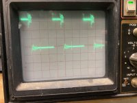
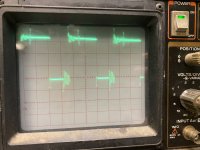
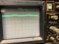
Here is what I get on the following
Q500,501,506,507
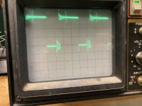
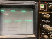
The last pic is what I get on Q502,503,504,505
Q500,501,506,507
The last pic is what I get on Q502,503,504,505
Attachments
-
 EF018160-F3D0-432D-B23F-9E16BC22F6E2.jpeg485.7 KB · Views: 48
 -
 2F6F5DAD-1A75-455F-AC00-58C1F3D10E9D.jpeg446.8 KB · Views: 49
 -
 B96FD625-222D-40CB-BA3C-9D78C606CF01.jpeg454.5 KB · Views: 46
 -
 165F8713-C1B7-42FC-B577-17A63759DAB6.jpeg412 KB · Views: 52
 -
 4723B459-1AFE-4E3C-A24E-E0A78D6FD4B3.jpeg470.4 KB · Views: 63
The high-side is floating. There should be no voltage on the source leg of the high-side FETs. Confirm and then (if there is o voltage) ground the scope probe to the FET source leg and re-check. This is best done in differential mode but using the ground clip will work if there is no voltage.
Q502: 126.1
Q503: 126.1
Q504: 71.7
Q505: 71.7
This is what I get on the source leg for the outputs (3rd leg)
Q503: 126.1
Q504: 71.7
Q505: 71.7
This is what I get on the source leg for the outputs (3rd leg)
Touch an incandescent lamp (one terminal connected to ground) to the high-side source pad. Does it light up?
No but I tried with a light bulb for a house .
I will get a 12 volt light bulb and try again
I will get a 12 volt light bulb and try again
Last edited:
That means there there is no voltage source connected to that pad. If you can't use your scope in differential mode, ground the source pad through the lamp and re-check the gate signal.
I don't see anything that could be causing a problem.
Try all again with a 0.01uF loading capacitor. You can ground the scope to the source pad for the low-side FET pads to get a cleaner signal.
Try all again with a 0.01uF loading capacitor. You can ground the scope to the source pad for the low-side FET pads to get a cleaner signal.
- Home
- General Interest
- Car Audio
- JL Audio 1000/1v2