The 180 ohm resistors give about 3mA that times 2 gives your 7 (give or take one) mA's. That's all functioning. Maybe it is a startup problem? the Vce of the low voltage parts could start conducting before the high voltage parts (Vce breakdown). Try the same with all high voltage parts and see. You can leave the resistor in place it will not be of a great influence. Also try to get the resistor down and see what the lowest 'working' value is. I can do some test myself, but not before the weekend 🙁 🙂
Very high impedance circuits can have problems.
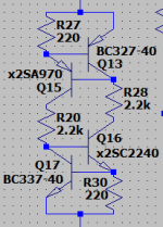
The extra resistor looks like emitter degeneration to me.
Have not seen that before but it seems to lower " distortion ".
So Ricardo found something usefull by " playing around ".
The extra resistor looks like emitter degeneration to me.
Have not seen that before but it seems to lower " distortion ".
So Ricardo found something usefull by " playing around ".
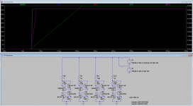
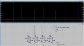
according to this sim, your new ccs version seems much stiffer than the "usual" two NPN arrangement (that I built just for Learning purposes)
The "usual" one works flawlessly but it's current highly dépends on Vcc.... going from 35v to 70v almost doubles ccs current.
According to the sim, FdW ccs does not suffer from this "illness". It stays put whatever Vcc I use 🙂
The "usual" one works flawlessly but it's current highly dépends on Vcc.... going from 35v to 70v almost doubles ccs current.
According to the sim, FdW ccs does not suffer from this "illness". It stays put whatever Vcc I use 🙂
Attachments

Green line is the "usual" ccs..... purple line is the improved FdW design.
PS: I modified the resistor values because I am searching for 7mA ccs (the same I get with the actual 10k resistor in my stock build.)
PS: I modified the resistor values because I am searching for 7mA ccs (the same I get with the actual 10k resistor in my stock build.)
... FdW ccs does not suffer from this "illness". It stays put whatever Vcc I use 🙂
That's what I like 🙂 calling it then 'FdW ccs' like I invented it. Actually I did do a lot of Google-ing to see if there is any pre-existing art and I could find nothing.
My question here is; 'Is there anyone here (or somewhere else 🙂) that knows of any prior existence if this CCS?', let me know!
Good news..... just finished breadboard example and it works perfectly with 35v psu producing 7mA 🙂 (mouche)
Now I will try it with 70v
Now I will try it with 70v
It goes without saying.... of course it works with 70v.
Now I will build the two ccs to implement in the amp 🙂
Now I will build the two ccs to implement in the amp 🙂
Well, I will now record some measurements on the stock build and post them here.
Will do the same after each mod.
First mod is the ccs, second one will be reducing miller cap and finally the bias circuit.
Lots of work, loads of fun.... in the end I will have collected a lot of knowledge and hopefully get a fine sounding power amp.
Will do the same after each mod.
First mod is the ccs, second one will be reducing miller cap and finally the bias circuit.
Lots of work, loads of fun.... in the end I will have collected a lot of knowledge and hopefully get a fine sounding power amp.
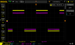
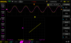
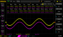
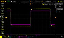
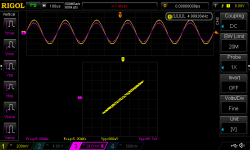
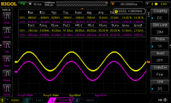
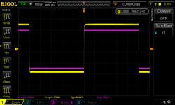
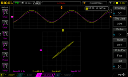
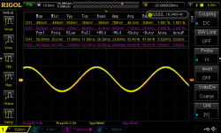
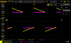
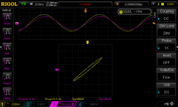
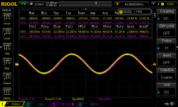
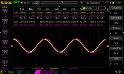
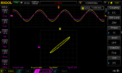
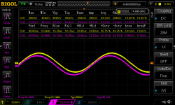
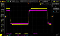
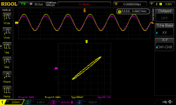
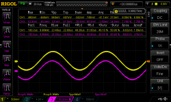
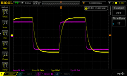
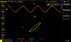
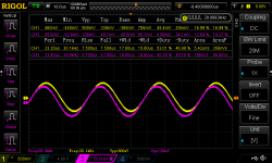
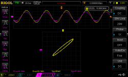
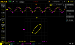
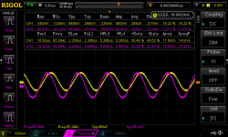
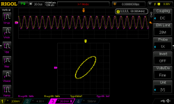
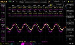
My measurements done with 100mv input and a "real" 8ohm speaker load. (Do not know if using a resistive load would change things significantly)
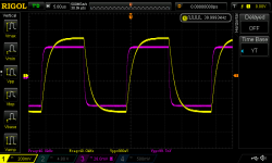
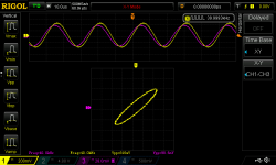
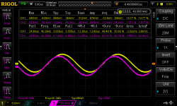
From 200Hz to 5KHz things look quite good
From 200Hz to 5KHz things look quite good
Attachments
-
 DS1Z_200hz square.png37.1 KB · Views: 93
 -
 DS1Z_200hz lissajous.png39.5 KB · Views: 94
 -
 DS1Z_200hz 100mv sin.png48.8 KB · Views: 91
 -
 DS1Z_5khz square.png36.6 KB · Views: 79
 -
 DS1Z_5khz lissajous.png40.9 KB · Views: 160
 -
 DS1Z_5khz 100mv sin.png49.9 KB · Views: 169
 -
 DS1Z_1khz square.png34.4 KB · Views: 162
 -
 DS1Z_1khz lissajous.png39.4 KB · Views: 160
 -
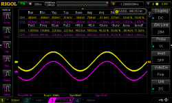 DS1Z_1khz 100mv sin.png49 KB · Views: 181
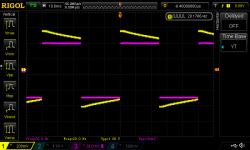
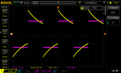
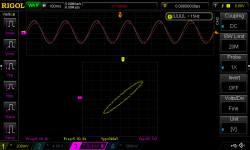
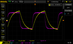
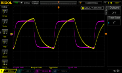
At 5Hz 10Hz and 20Hz I notice Low frequency loss and phase shift, no amplitude distortion but out of phase.
Attachments
-
 DS1Z_20hz square.png37.5 KB · Views: 86
 -
 DS1Z_20hz lissajous.png38.2 KB · Views: 86
 -
 DS1Z_20hz 100mv sin.png45.5 KB · Views: 84
 -
 DS1Z_10hz square.png37.5 KB · Views: 80
 -
 DS1Z_10hz lissajous.png38.3 KB · Views: 77
 -
 DS1Z_10hz 100mv sin.png46.1 KB · Views: 81
 -
 DS1Z_5hz square.png37.9 KB · Views: 81
 -
 DS1Z_5hz lissajous.png38.5 KB · Views: 77
 -
 DS1Z_5hz 100mv sin.png47.6 KB · Views: 100
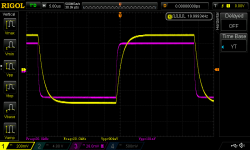
At 10khz and 15khz gain is still max but we start to have high frequency loss and phase shift , without amplitude distortion but out of phase.
Attachments

At 20kHz gain starts to lower from top 20dB (19dB at 20k) and the trend is accentuated (high frequency loss and phase shift , without amplitude distortion but out of phase)
Attachments
-
 DS1Z_40khz square.png39.7 KB · Views: 80
 -
 DS1Z_40khz lissajous.png38.3 KB · Views: 71
 -
 DS1Z_40khz 100mv sin.png48.2 KB · Views: 83
 -
 DS1Z_30khz square.png38.3 KB · Views: 72
 -
 DS1Z_30khz lissajous.png38.1 KB · Views: 76
 -
 DS1Z_30khz 100mv sin.png49 KB · Views: 72
 -
 DS1Z_20khz square.png37.3 KB · Views: 86
 -
 DS1Z_20khz lissajous.png41.5 KB · Views: 88
 -
 DS1Z_20khz 100mv sin.png47.9 KB · Views: 86
At very high frequencies we notice high frequency loss and low frequency phase shift (no amplitude distortion but out of phase).
Attachments
- Status
- Not open for further replies.
- Home
- Source & Line
- Analogue Source
- JG´s Nobrainer and Nobrainer Discrete