The zeners and the diode form the voltage reference.... the setup aims for lowish impedance and temp compensation.
The transistor and the cap before the reg form a cap multiplier.... it works, I have used this for +- 15v in my cdp..... powering the output opamps....
But it is no cap multiplier 🙁 and I'm sure it will work as a 15V supply, the BC's change nothing about that!
Last edited:
The zeners and the diode form the voltage reference.... the setup aims for lowish impedance and temp compensation.
The parallel zeners do not improve anything (they would if the matching was 100% (0% difference) but they are not 🙁 and even then ... mmm (doubts expressed 🙂)) Anyway long term thermal stability is not a problem (over periods of minutes even seconds). I would guess that modern day 317/337's are even more stable then the zener(s)/diode.
Found some D44 D45 power trannies in my stock... good... now I have an old Meridian 101 PSU that I would like to use in this project.... the output is +-35v so it is too much for the opamp.... can I use LM317 337 to feed the opamp at 18volts ?
When powering down, the capacitor is emptied through the BC's base-emitter diode, that is not advisable. To be a capacity multiplier you need some voltage drop between the BC's collector and base. On sudden large current demands, the output power is supplied through the BC's base-emitter diode (not good).
Ok, this was an old idea that I used 10 years ago.... you know better than me of course... I will use the standard 317 layout 🙂
How much current can the opamp draw from the psu ?
I am really considering using the kmult to filter but it needs enough current to work best.
I am really considering using the kmult to filter but it needs enough current to work best.
Yes, otherwise the kmult will struggle, but now it seems to add too much complexity.
I will try the "normal" 317 reg first.
I will try the "normal" 317 reg first.
OK, good. The new National opamps have very good PSU rejection anyway.
I use a little trick i learned from Bonsai.
Use 22 Ohm resistors in series with PSU plus and minus and decouple with 220uF each.
I then use only one 0.1uF foil from plus to minus for HF decouple ( Self ).
That way you improve PSU rejection in the treble where PSSR of the opamp gets worse.
I use a little trick i learned from Bonsai.
Use 22 Ohm resistors in series with PSU plus and minus and decouple with 220uF each.
I then use only one 0.1uF foil from plus to minus for HF decouple ( Self ).
That way you improve PSU rejection in the treble where PSSR of the opamp gets worse.
I then use only one 0.1uF foil from plus to minus for HF decouple ( Self ).
That way you improve PSU rejection in the treble where PSSR of the opamp gets worse.
Where do these 0.1uF go ?
plus to minus near the opamp Voltage inputs ?
Where do these 0.1uF go ?
plus to minus near the opamp Voltage inputs ?
🙂 as used in my power amp
Attachments

So I got it right 🙂
This will be a blast 🙂
You did not got it wrong 🙂 say no more...
Monty Python - Nudge Nudge Wink Wink Say No More - YouTube
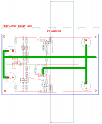
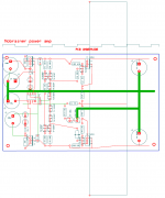
Here we have my first p2p draft.
Please comment on the component's layout and particularly on their pinout.
PS: Should the drivers be placed in contact with the heatsink ?
Please comment on the component's layout and particularly on their pinout.
PS: Should the drivers be placed in contact with the heatsink ?
Attachments
Last edited:
Would you care to verify pinouts of the opamp and output trannies... this is the copper side view btw.... I would really appreciate that and maybe I will save a lot of trouble 🙂
- Status
- Not open for further replies.
- Home
- Source & Line
- Analogue Source
- JG´s Nobrainer and Nobrainer Discrete