Sure this is a good idea? This simply adds a stage to only one of the amps - not good for symmetry.When i understand you correct i whould then modify the amps for inverted. See Old - New.
Then i whould add a buffer for both channels and an inverter to one channel to make a bridge.
I like the DRV134 approach - much more "equal" on both sides.
Sure this is a good idea? This simply adds a stage to only one of the amps - not good for symmetry.
I like the DRV134 approach - much more "equal" on both sides.
Yes, that would be VERRY-balanced, but at a big cost, and I am sure that the inverting amp with a gain of 1 cannot be heard (or measured). As an experiment it would be nice to try, build one as shown now, and build one with the ina's (as a matter of fact that is (more or less) what I am currently doing, you may have seen my pcb’s in the mpp thread http://www.diyaudio.com/forums/analogue-source/154210-mpp-300.html#post3043904).
The DRV134 also has 6dB of gain, that comes from the balanced anyway.
Ok, both amps inverted plus the DRV134, that could then also easily compared to the non inverting amp i use now.
Ok, both amps inverted plus the DRV134, that could then also easily compared to the non inverting amp i use now.
See also Simplest Ever Bridging Adapter for Amplifiers. (I needed to show that, no extra amp needed 🙂)
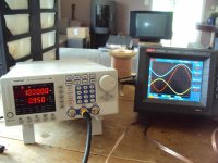
Just for fun i did the simplest bridge and it works. Into 6.6 Ohm i get now 22W, RMS. That is 34V P-P and 12V RMS. Into 3.3 Ohm the power does not double because the current limit sets in. I calculate about 4.2A, that is decent.
This is only an experiment. I decided to build 2 more SBPs and do them all inverted plus DVR134. That will give the best symmetry and the best technical performance.
This is only an experiment. I decided to build 2 more SBPs and do them all inverted plus DVR134. That will give the best symmetry and the best technical performance.
Attachments
Just for fun i did the simplest bridge and it works. Into 6.6 Ohm i get now 22W, RMS. That is 34V P-P and 12V RMS. Into 3.3 Ohm the power does not double because the current limit sets in. I calculate about 4.2A, that is decent.
This is only an experiment. I decided to build 2 more SBPs and do them all inverted plus DVR134. That will give the best symmetry and the best technical performance.
That's the 'Elliott' one? Any sound impression?
I do think that the 49710 input + 49710 inverter will be performing better than the 134. For one the 49710 is a better opamp, and for two the signal in the 134 goes through an inverting (one side) and an non inverting (the other side) amp, and that is +/- (about) the same.
Yes, that is the Elliott. I did not listen to it because it is only mono. I have to build a second set.
Which version sounds better i have no idea. Maybe we should arrange a shootout, the different circuit are quite easy to implement.
I could also do some distortion measurements but i usually do listen first to be not so prejudiced.
Which version sounds better i have no idea. Maybe we should arrange a shootout, the different circuit are quite easy to implement.
I could also do some distortion measurements but i usually do listen first to be not so prejudiced.
I started now to build the two other channels. I will build them non inverting like the first ones and do the Elliott trick. I have put this little amp now over 80Hz on my 95dB panels i have build for the ETF. Now decent volume is possible. I must say that i can not complain.
The amp sounds neutral and well resolved with a small measure of warmth.
When we do the PCB we can include the option of inverted and also current drive but at the moment i have no desire to change it.
The amp sounds neutral and well resolved with a small measure of warmth.
When we do the PCB we can include the option of inverted and also current drive but at the moment i have no desire to change it.
I studied Douglas Self´s Audio Power Amplifier Design Handbook for the 100 x time.
He is an advocate of the CFP stage i use here too. This stage works best in Class B and Class A. Class A/B curiously gives the highest distortion. Also it is quite clear that lowering the value of the emitter resistors ( actually here they are on the collectors of the output transistors ) to the lowest practical value that gives thermal stability has an advantage in terms of crossover distortion and also drives low impedance loads better. How the bias is set is somewhat unclear. In the mathematical example with 0.1 Ohm resistors it is 3.06mV over both resistors. That is only 18mA of bias. A bit hard to set because there is some 10% tolerance in the emitter resistors and even some mV of offset ( fortunately low ) can screw that up badly. Stabilizing that thermally is not easy ether. In his Trimodal Amp he sets that value to 10mV in praxis. That seems more reasonable also in the view that a CFP output is somewhat less sensitive to over bias ( what a name ! )then a conventional double emitter follower ( Darlington ). So we end up with 50mA. That is reasonable. Lets see what sounds better, more or less bias.
He is an advocate of the CFP stage i use here too. This stage works best in Class B and Class A. Class A/B curiously gives the highest distortion. Also it is quite clear that lowering the value of the emitter resistors ( actually here they are on the collectors of the output transistors ) to the lowest practical value that gives thermal stability has an advantage in terms of crossover distortion and also drives low impedance loads better. How the bias is set is somewhat unclear. In the mathematical example with 0.1 Ohm resistors it is 3.06mV over both resistors. That is only 18mA of bias. A bit hard to set because there is some 10% tolerance in the emitter resistors and even some mV of offset ( fortunately low ) can screw that up badly. Stabilizing that thermally is not easy ether. In his Trimodal Amp he sets that value to 10mV in praxis. That seems more reasonable also in the view that a CFP output is somewhat less sensitive to over bias ( what a name ! )then a conventional double emitter follower ( Darlington ). So we end up with 50mA. That is reasonable. Lets see what sounds better, more or less bias.
I studied Douglas Self´s Audio Power Amplifier Design Handbook for the 100 x time.
He is an advocate of the CFP stage i use here too. This stage works best in Class B and Class A. Class A/B curiously gives the highest distortion. Also it is quite clear that lowering the value of the emitter resistors ( actually here they are on the collectors of the output transistors ) to the lowest practical value that gives thermal stability has an advantage in terms of crossover distortion and also drives low impedance loads better. How the bias is set is somewhat unclear. In the mathematical example with 0.1 Ohm resistors it is 3.06mV over both resistors. That is only 18mA of bias. A bit hard to set because there is some 10% tolerance in the emitter resistors and even some mV of offset ( fortunately low ) can screw that up badly. Stabilizing that thermally is not easy ether. In his Trimodal Amp he sets that value to 10mV in praxis. That seems more reasonable also in the view that a CFP output is somewhat less sensitive to over bias ( what a name ! )then a conventional double emitter follower ( Darlington ). So we end up with 50mA. That is reasonable. Lets see what sounds better, more or less bias.
To measure bias you can insert a resistor in the power line and measure it there.
I will do the emitter resistors from several 1 Ohm metal films in parallel. I think that way i can measure the idle indirect by measuring the voltage over them. Your idea is good too.
I am more concerned if i can stabilize that low amount of idle and how it sounds. I think i have to measure distortion in the end.
I am more concerned if i can stabilize that low amount of idle and how it sounds. I think i have to measure distortion in the end.
To measure bias you can insert a resistor in the power line and measure it there.
The thing about this is, you can use (almost) any value (even up to 10 Ohms) if you add a buffer capacitor on the south side (PSU on the north side 🙂). So even with an less expensive multimeter you get good results (I'm sure you have a good one (I did see a picture of your UNI-T somewhere 🙂)). Using a high'ish resistor will also help keep the smoke in the output device when things go pear-shaped. http://en.wikipedia.org/wiki/Pear-shaped
Last edited:
Yes, i have a big UNI-T. I bought it to measure input offset on my phono stages. I think it goes down to 0.01mV.
I am building two more channels of the SBP to make a bridged amp. I also experimented with Bias and Output Inclusive Compensation.
I got now better and bigger heat sinks so i set the Bias at around 500mA. That gives 4W in Class A into 8 Ohm per module. I will listen if that sounds better. I will also try Class B as recommended by D.Self. That is then less then 50mA of Bias.
The Output Inclusive is kind of interesting. I was afraid that it could make the amp unstable into capacitive load but the contrary happened. Putting a 0.33uf across a 6.6Ohm resistor there was barely any change visible with a 10kHz square. What it also does is slowing down the amp. The -3dB frequency in the treble is aproximately cut in half. It also seems that the rolloff has a higher order so until 20kHz there is not much loss compared to the miller compensated version. Both effects have not being described by Self in the Linear Audio 0 article and may be due to the fact that i use a different topology. I could of cause half the Miller caps and get the speed back.
As simple as this little thing is, building the SBP is fun and i am still learning.
I am building two more channels of the SBP to make a bridged amp. I also experimented with Bias and Output Inclusive Compensation.
I got now better and bigger heat sinks so i set the Bias at around 500mA. That gives 4W in Class A into 8 Ohm per module. I will listen if that sounds better. I will also try Class B as recommended by D.Self. That is then less then 50mA of Bias.
The Output Inclusive is kind of interesting. I was afraid that it could make the amp unstable into capacitive load but the contrary happened. Putting a 0.33uf across a 6.6Ohm resistor there was barely any change visible with a 10kHz square. What it also does is slowing down the amp. The -3dB frequency in the treble is aproximately cut in half. It also seems that the rolloff has a higher order so until 20kHz there is not much loss compared to the miller compensated version. Both effects have not being described by Self in the Linear Audio 0 article and may be due to the fact that i use a different topology. I could of cause half the Miller caps and get the speed back.
As simple as this little thing is, building the SBP is fun and i am still learning.
I think that 50mA is a bit low (but I'm not D. Self 🙂). Check the datasheet of the power device and like here ON Semiconductor MJL4281A: NPN Audio Bipolar Power Transistor you may see a '•Gain Linearity from 100 mA to 5 A' like specification (or you should interpret the graphs in the datasheet), select this minimum as your minimum for 'B'-like operation of the amp (in this case 100mA).
Yes Frans, that is true for an EF follower ( Self give somewhat over 100mA, depending on the emitter resistors, that has to do with that famous 24,5mV ) but this is a CFP ( Szikley ) with 100% feedback so optimum bias is much lower if you do not bias high into Class A.
What is different to Self´s output stage is that i degenerate the drivers much more. I use 100
Ohm and he uses 10 to zero Ohm. That of cause lowers the voltage gain ( in my case it should have 1x, so no voltage gain) but it helps to linearize, a trick i copied from JLH.
Another reason i do that is to lower the current that is supplied by the drivers that go into the load. That way i can use high speed small signal transistors. What effect that has on the optimum BIAs i can not tell at the moment. In JLHs books i have not found how to bias that variety optimum.
- Status
- Not open for further replies.
- Home
- Source & Line
- Analogue Source
- JG´s Nobrainer and Nobrainer Discrete