Magura said:
The square looks pretty ok till 50Hz, the sine looks fine as well.
To my ears, it offers just about anything I've ever wanted.
Magura 🙂
That's more than good enough for my high-frequency amplifier...🙂
Are these chokes the enormous fellows I saw a year ago, or did you wind anew with smaller wire?
carpenter said:
That's more than good enough for my high-frequency amplifier...🙂
Are these chokes the enormous fellows I saw a year ago, or did you wind anew with smaller wire?
These are new chokes, smaller wire gauge and a **** of a lot of turns.
Magura 🙂
Zen Mod said:
...if ya don't know that simple it is : L= Z/(2 x Pi x F) ........so - 5K/(2Pix20)=39H...
Nifty formula, thanks.
If I wanted to lower the drain resistor to 2.2k I can use a much smaller choke. How do you determine the optimum drain resistance?
I remember lowering the drain resistor value to 1.5k, which would lower the choke value even more.
Perhaps I start with my favorite resistor value in the bread-board experiment, then substitute its value in the formula when I want to insert a choke?
carpenter said:
did you wind anew with smaller wire?
It just dawned on me, there are pics of such inductors here at diyaudio.
Look at Steen's birthday present to get a hint about the size.
Magura 🙂
Magura said:
It just dawned on me, there are pics of such inductors here at diyaudio.
Look at Steen's birthday present to get a hint about the size.
Magura 🙂
Ooooh, I saw that pic earlier this month--nice job Kemosabe! 😀
I've been playing with Micro-Cap. Wonderful freebie! It's a bit limited in its "evaluation" mode. Still, I discovered the correct jfets and substituted an IRF510 fet for the CCS. This has been a lot of fun!
Now, can I justify spending $4600.00 on the commercial product?!😱 😀
I'd like to learn how to install the necessary spice transistor models and avoid the high purchase expense--mind you, I think I'll have to donate something to Micro-Cap for the shear joy I've had in the last week--not to mention, the rest of my life. Wow.....
Attachments
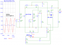
Wow Carpenter, good work ! Can you do Fourier or THD outputs too? You might think about adding a load R at the "OUT" node. Like 10K or 47K or whatever you would plug this into... You might also find the C1 and C6 need to be bigger for lower freq response 😀
Can you edit your models? You may be able to create your own manually by copying the data from a Spice model into you MC model editor...
Can you edit your models? You may be able to create your own manually by copying the data from a Spice model into you MC model editor...
Hi Lee,
Thanks for the comments. In the tests, I believe I used a 50k load in addition to the 3k load. Also, I forgot to change the caps back to 10uF--they were originally 10uF.
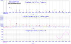
This software predicts THD--seems to me it read lower with the 1uF cap--that's why I lowered the cap value in the first place. Since this is a high-frequency amplifier/gain-stage package, the smaller cap won't be a problem.
This gain-stage had very little distortion.
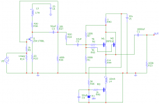
I also ran the simulation with dual jfet CCSs. I discovered wonderful results are possible with fewer components. Distortion readings were excellent.
For the mid-bass amp, I'll have to make some cap adjustments. I'll post a pic of the test results.
There's a lot more for me to learn, but this software comes with 15 or more excellent active tutorials. In time, I'll have this baby wired. Like Nelson wrote, I'll be using this tool for the rest of my life. Now, I'm not groping in the dark......
Wow. Thanks, Nelson, for turning me on to Micro-Cap.🙂
Thanks for the comments. In the tests, I believe I used a 50k load in addition to the 3k load. Also, I forgot to change the caps back to 10uF--they were originally 10uF.
This software predicts THD--seems to me it read lower with the 1uF cap--that's why I lowered the cap value in the first place. Since this is a high-frequency amplifier/gain-stage package, the smaller cap won't be a problem.
This gain-stage had very little distortion.
I also ran the simulation with dual jfet CCSs. I discovered wonderful results are possible with fewer components. Distortion readings were excellent.
For the mid-bass amp, I'll have to make some cap adjustments. I'll post a pic of the test results.
There's a lot more for me to learn, but this software comes with 15 or more excellent active tutorials. In time, I'll have this baby wired. Like Nelson wrote, I'll be using this tool for the rest of my life. Now, I'm not groping in the dark......
Wow. Thanks, Nelson, for turning me on to Micro-Cap.🙂
Very Good 😀 I use Pspice with a schematic editor called "Schematics". It's a little easier than the OrCAD capture when using Pspice. That's all I've ever used. Maybe I'll download M-Cap and give it a try...
I noticed your devices are called ...BL. My library just has 2SK170 & 2SJ74s Do you actually know their Idss? If you don't, it's easy to make a simple test circuit sim with just the JFET and a DC supply. Tie it's gate to it's source and put 10Vdc across it and measure the current. That would be Idss 😀 The Idss of the standard models in my Pspice is about 11.5mA or something. You would do the same test to measure/match devices for real...
Looks like your output waveform has a little distortion on the first neg 1/2 cycle? I've seen stuff like this in Pspice too? I think it's something to do with getting to the proper DC bias point before doing AC anaysis? The bigger caps will make it worse. I ussually get around it by providing some DC offset on the other side of the cap so it does not have to charge up at all. I'm not sure you can do this in your circuit? Another option is to set the analysis for more total time or cycles. Then the first distorted cycle or two average into the longer time and have less effect on the total.
flg said:Very Good 😀 I use Pspice with a schematic editor called "Schematics". It's a little easier than the OrCAD capture when using Pspice. That's all I've ever used. Maybe I'll download M-Cap and give it a try...
I noticed your devices are called ...BL. My library just has 2SK170 & 2SJ74s Do you actually know their Idss? If you don't, it's easy to make a simple test circuit sim with just the JFET and a DC supply. Tie it's gate to it's source and put 10Vdc across it and measure the current. That would be Idss 😀 The Idss of the standard models in my Pspice is about 11.5mA or something. You would do the same test to measure/match devices for real...
Looks like your output waveform has a little distortion on the first neg 1/2 cycle? I've seen stuff like this in Pspice too? I think it's something to do with getting to the proper DC bias point before doing AC anaysis? The bigger caps will make it worse. I ussually get around it by providing some DC offset on the other side of the cap so it does not have to charge up at all. I'm not sure you can do this in your circuit? Another option is to set the analysis for more total time or cycles. Then the first distorted cycle or two average into the longer time and have less effect on the total.
Excellent ideas, Lee. I'll try them out and get back to ya. Yes, the 2Sk170 is a BL device. I'll post a snap-shop of the distortion page soon. I think that the distortion in the first output waveform is in part due to the high-gain of the circuit. The distortion seems lessened when I lower the gain.
I'll take all the info you've got on using Micro-Cap, if/when you get around to giving it a try.
John
😀
That sounds correct.carpenter said:
... The distortion seems lessened when I lower the gain.
😀
I've been experimenting with Micro-cap while convalescing (I fell backwards into a six foot deep crawlspace through a floor I was framing 😱 Unfortunately, I landed on the shoulder that had been injured six months ago...back to square one.)
So here's my ideas. I would love to hear what my fellow diyers think.🙂
So here's my ideas. I would love to hear what my fellow diyers think.🙂
Attachments
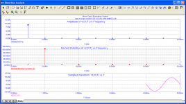
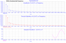
If I correctly recall, the second harmonic distortion spec is located at the 2k reading point on the graph; third harmonic distortion is located at the 3k reading. I'll attempt to verify that information. If my thoughts are correct the second harmonic distortion is quite low (0.15 percent) and the third harmonic is almost non-existent. This seems quite good considering it's taken pretty much at full output.
Sorry to hear about your fall. That does not sound fun at all. At least you have some good toys to play with while you recuperate.
Toys, yes! I think M-Cap is the most amazing piece of software I've ever used. I just wish I could afford to purchase the full package. $4500.00 is a bit steep for me.
Thanks for the condolences, Dave.
Thanks for the condolences, Dave.
- Home
- Amplifiers
- Pass Labs
- JfetBOZ mods