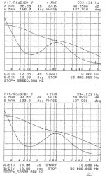
I finally managed to snag the cap values I needed, so I was able to change out the RIAA equalization network and get the 1kHz gain close to 40dB at 1kHz, which is what I like to see for home use. Attached are the gain-phase plots for both sides of the RIAA preamp with the new equalization values - matching between channels is still pretty close (~0.1 dB). I'll continue with these equalization network values for further experiments.
For the broadcast setup I'm contemplating, I'll use a unity gain line amp, and lower gain for the RIAA stage, as the broadcast cartriges are hotter than a lot of the standard hi-fi cartridges. I'll probably change out the gain fets in the SRPP stage to lower the phono preamp gain. Possible candidates are my old friend the PN4393, and the J309. Both of these fets have low gate capacitance and reasonably low noise.
For the broadcast setup I'm contemplating, I'll use a unity gain line amp, and lower gain for the RIAA stage, as the broadcast cartriges are hotter than a lot of the standard hi-fi cartridges. I'll probably change out the gain fets in the SRPP stage to lower the phono preamp gain. Possible candidates are my old friend the PN4393, and the J309. Both of these fets have low gate capacitance and reasonably low noise.
Attachments
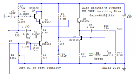
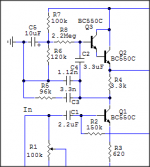
Here is the RIAA circuit with the new equalization values to bring down the gain to ~40dB at 1kHz. The caps are a mixture of store-bought (Wima FKP2 PP film/foil) and scrounge (polystyrene laid-in lead units from (?) and TRW). I'll be listening to this thing sooner or later, and will report on the results.
Attachments
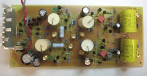
You need some better glasses - there are 8 connectors - 2 channels, an RIAA preamp and line amp for each one - with ins and outs, it all adds up...
There's only one thing I don't like about the single-stage SRPP phono preamp - it's inverting. This means that in a multiple source situation, the phono will always be opposite in phase from any other signal source. That may (or may not) be fixable by rewiring the tonearm, but what a PITA.
I spent some of this evening doing the soldering on the studio version of this preamp, which will feature a lower gain RIAA stage for the hotter broadcast cartridges, and a unity gain line amp stage that will eventually drive output transformers for a balanced feed to the studio A/D converter.
I need to look more closely at the pictures. It seemed odd, but I didn't even take a second look.
You need some better glasses - there are 8 connectors - 2 channels, an RIAA preamp and line amp for each one - with ins and outs, it all adds up...
I just put the home version of the RIAA/Lineamp all-in one package into my living room test case and powered it up for an hour or so with a bench supply to check for bias stability - all's well so far. Next thing is to hook up all my components and let it play - fingers crossed, as I've done a fair number of measurements with a lot of equipment except for my ears...
I made a remark that it didn't appear to make any difference in the position of the 10uF coupling cap between top and bottom stages of the single stage SRPP preamp - well, it looks like I'll have to eat that remark.
Attached is a pic with the two schematics in question, the being the position of the 10uF interstage coupling cap. Casual inspection would make one think that there would be no substantial difference in the frequency response of the two circuits (marked "A" and "B"). Simulation and real-life test indicates otherwise.
So you know what I'm talking about, the attached picture shows the two schematic variants in question. They vary regarding the position of the 10 uF interstage coupling cap (C5) vs. the RIAA comp network. The connection difference is subtle.
Attachments
Last edited:
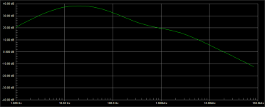
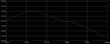
Attached is the freq response from circuit B, the first variant I tried - notice the peak near 10Hz, and how high it is. This combined with the tonearm resonance and some acoustic feedback (turntable isolation is pretty lousy) had my woofers flapping around like Dumbo's ears. Very disconcerting...
Attachments
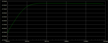
Here is the frequency response for circuit variant "A" - note that the 10Hz amplitude is lower and that the plot looks like a LF round-off rather than a resonant peak. The actual circuit (cut and jumpered into shape) is much more well-mannered, though Dumbo will still flap his ears if the volume is high enough, indicating that there is some turntable damping/isolation/resonance tailoring left to do.
Attachments
I wonder if the designer of the original Creek preamp ran into the same issues? In a way, I'm glad I ran into this problem, as it will be a learning experience once I figure out what's happening.
This is just an initial remark, but we are used to thinking of things in terms of voltage dividers. If you consider the circuit as a frequency-dependent current divider driven by a voltage-dependent current source, the differences between the two circuits may make more sense. Surely the cascoded bottom jfet can be modeled with a good degree of confidence as a current source - after all, that's what cascoding is about...
I wonder if the designer of the original Creek preamp ran into the same issues? In a way, I'm glad I ran into this problem, as it will be a learning experience once I figure out what's happening.
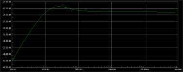
Surely the card worked without VLF exaggeration, and here is the simulation of the tweaked circuit I had posted in another thread. Attached here again for quick reference.
Attachments
Well yeah, the circuit you show (and the original Creek preamp) has the coupling cap configured like circuit "A", which has the smooth roll-off (shown in post #212) without VLF peaking. Try switching the coupling cap (C2) around in Nitikin's circuit so that it's like "B" and see if there's a difference - I'm curious.
I'm also wondering if the cascoding I'm using makes any difference. If I have time tonight, I'll strip the cascode first from the top jfet, then the bottom, and see what happens. The circuit you show has no cascoding at all. If I remember correctly, the better Creek circuit cascoded the bottom jfet, but not the Darlington on top.
I'm also wondering if the cascoding I'm using makes any difference. If I have time tonight, I'll strip the cascode first from the top jfet, then the bottom, and see what happens. The circuit you show has no cascoding at all. If I remember correctly, the better Creek circuit cascoded the bottom jfet, but not the Darlington on top.
Last edited:
Very mysterious, it looks like the two implementations in your case are pretty close to identical, with a smooth low-frequency roll-off and a small gain difference. This is what one would expect from a casual look at the circuit. I'll have to try the same circuit you did in both "A" and "B" variations to see if I get the same answers, as we look to be using different simulation engines (PSpice/Orcad in my case). If I get the same answers as you, I'm going to try monkeying around with the cascodes on my circuit to see what I get.
BTW, I thought the fet used in the OBH8SE was the J110, but my schematic copy is not exactly razor-sharp, so its kinda hard to tell "eights' and "threes' from zeros. Both fets would be reasonable in that application, though I suspect the J110 would have more gain than the J113. I just recently bought a bunch of NXP J113s for messing-around purposes, as Mouser still had them in stock in TO-92 package, and I have some NOS National (?) parts in the basement somewhere...
BTW, I thought the fet used in the OBH8SE was the J110, but my schematic copy is not exactly razor-sharp, so its kinda hard to tell "eights' and "threes' from zeros. Both fets would be reasonable in that application, though I suspect the J110 would have more gain than the J113. I just recently bought a bunch of NXP J113s for messing-around purposes, as Mouser still had them in stock in TO-92 package, and I have some NOS National (?) parts in the basement somewhere...
Last edited:
- Home
- Source & Line
- Analogue Source
- JFET SRPP RIAA Preamp