Not really dirting on the 2SK170 - a nice, useful, part, with plenty of applications. It probably won't shine best in an SRPP, though.
I'm looking at a simple discrete setup to replace the discrete opamp RIAA preamps I did for the college radio station where I DJ as a hobby (they've been in place for about 10 years, and I can do better now). I'll probably settle for a simple cascoded common source amp in the front end using 2SK170s (good performance, low parts count). I haven't settled on the output end yet - I've given myself too many choices.
The 2SK170s will work well in the apps you've talked about, but you can use less fancy fets for something like a line level active crossover and save the scarce, fancy parts for something where you really need them.
I started out this whole nest of related RIAA threads a few years back with a modified Pacific preamp, documented here somewhere ("open loop follies"), using the 2SK170. As I recall, I couldn't find my sorting jig at the time (moving does that to you), so I might have sorted the fets via matching for IDSS. I have that preamp board sitting on my dining room table as I write this. I may haul it in to work tomorrow to do a gain-phase plot and append it to the original thread, as that thread got tangled up in side issues and I branched out into other pursuits, so if I did a plot (probably), I never added it. It would be useful documentation to see the gain and channel-channel matching of that simple setup. It would also be amusing to put together a photo- menagerie of all the boards I've done in the meantime with links to the threads, as they're probably all lurking around the house somewhere.
I've got the Beige Bag disc floating around, but I use PSpice, as I've gotten used to it at work. LT Spice would also be an interesting alternative (free, too, with a large user community), and possibly less finicky than PSpice as far as importing models is concerned. Beige Bag may also be better in that respect than PSpice, as it wasn't saddled with the Orcad Capture interface like PSpice. I have LT Spice sitting on my computer here, but I really haven't had a lot of spare time to get used to it. Also less incentive, as I already have a big library of PSpice simulations where I can cut and paste and build up circuits quickly.
This is the data for a 2SK170 SRPP, set for a gain of 80X. Note the small value of load resistor required to tone down the gain.THD is ok, but nothing really to shout about. I started out with a 40X gain implementation (about 1/2 the value of load resistance), and the distortion is similar. A PN4303 or 2SK30 implementation would kick its sorry behind in all respects except for noise.
Attachments
The comparison of the Cascoded k170 with the SRPP k170 shows:
the same parts count.
Almost the same distortion.
less odd harmonics for the SRPP.
And the possibility of less noise for the SRPP.
How would a comparison for an SRPP with gain set to 200 (+46dB) or 500 (54dB) against any more suitable high gain stage?
the same parts count.
Almost the same distortion.
less odd harmonics for the SRPP.
And the possibility of less noise for the SRPP.
How would a comparison for an SRPP with gain set to 200 (+46dB) or 500 (54dB) against any more suitable high gain stage?
Huh? Post 162 shows the distortion distribution for the SRPP. Post 163 shows the harmonic distribution for the cascoded common source. The common source amp clearly has lower amplitude higher harmonics.
The SRPP requires 2 matched pairs for 2 channels. The common source amp only needs one pair. Parts count is about the same, but PITA level is far less for the common source. Obviously, you're not going to need matching of the cascode fets in the common source stage for DC balance. The cascode fets may not even have that much effect on the gain. I just finished fixing my first attempt in this way (the board is almost 7 years old!), and I may get a chance to measure it tomorrow for gain balance between channels.
An example of a high gain (400X) SRPP is shown in post 132. This amp will be pretty useless without the cascoding (maybe not for MC use, but it's probably too noisy for that purpose). I'm not entirely sure that I could get practical DC balancing with that high a gain and the extra matching required by the cascode. I suppose if you want to break with tradition and throw a nasty IC into the mix, you could servo the SRPP, but that sort of flies in the face of the whole spirit of the thread. Having said that, though, it would probably work.
Edit - the SRPP shown in post 162 using the 2SK170 will probably need cascoding to lower the effect of the Miller capacitance - that would drive up parts count and PITA factor.
Last edited:
Wrench,
I have looked again at posts162 & 163. I was comparing Normalised phase.
Sorry, ignore me.
I have looked again at posts162 & 163. I was comparing Normalised phase.
Sorry, ignore me.
In another thread in this forum a list member left me a link to a schematic for a Creek jfet/bipolar mixed SRPP RIAA MM preamp that wrings all the juice necessary for 300mV output out of one SRPP stage. Attached is a circuit that adapts the original circuit to all-jfet operation with symmetric cascoding. Using fixed bias on the top stage solves the balance problem you get in the real world when using symmetric cascode on an SRPP stage. It also looks possible to use high gain fets and still balance the circuit. Better yet, it may not require all that rigorous a matching of the jfets. This occurs at the cost of a big cap (C5 - the Creek circuit used electrolytics, I'll use a film cap). The Creek circuit used selected J110s, I used my old buddy the PN4393, cascoded by PN4391s. The PN4393 has low enough input capacitance to make it attractive for use with MM cartridges. With some slight modification, the 2SK117 would also be a good choice because of low capacitance (lower than the 2SK170).
I haven't yet quite understood sufficiently how the RIAA network works against the rest of the circuit in order to calculate the right component values for myself, so I just scaled the values from the original schematic until a got a PSpice frequency response plot with 40dB gain at 1kHz. The frequency plot looks RIAA-ish, but I won't vouch for its accuracy at all .
This is strictly in the "food for thought" phase at present.
Attachments
Last edited:
Hi,
have simulated the Creek-like structures some time ago and found, that noise may be critical. On the other hand they are high-gain cells, that may spare a second conventional gain-stage.
jauu
Calvin
have simulated the Creek-like structures some time ago and found, that noise may be critical. On the other hand they are high-gain cells, that may spare a second conventional gain-stage.
jauu
Calvin
Is it c5 that makes it srpp?
Could you explain the stage by stage operation, so that I and others can understand how it works?
Could you explain the stage by stage operation, so that I and others can understand how it works?
I think that I can jigger the value of R2 (using a 2SK117 for J7 instead of PN4393) so that the noise contribution is relatively low.
There's no getting around using a fairly substantial value for R8, though, as C5 works against it to provide drive from the drain of J7 to the gate of J9 (that's what makes it SRPP). Adding the fixed bias to the top fet means that the drive from the bottom needs to be AC coupled.The values used (I used the same as in the Creek schematic) provide a little low-frequency roll-off, perhaps meant for rumble filtering in the original design.
Getting rid of the second stage is desirable. In all the passive equalization designs I've worked on, the second stage is the bastard factor in the design distortion-wise due to the higher signal levels. Most of my efforts in the past few years have been devoted to reducing the distortion of that stage. The real question is, can you do it all in one stage and not have it sound like crap? There are devotees of that Creek preamp that say it sounds really nice. Will it be the ultimate ? I doubt it. It may very well be quite listenable, though.
This is the MM preamp. I don't know what Creek used for the MC booster. Since you have one, could you take a peek under the hood?
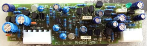
Its a an add on stereo card the specific one. Its either MM or MC set in manufacture. There is a newer one also based on op-amps fitting same amps I think. But this one is the SRPP. Mine has a small round sticker denoting if MM or MC. This in the pic I found on the web, since mine I don't even know where it is right now to photo it for you.🙂
Attachments
Having seen some of the pictures of the OBH-8/9 board on the web, I have a feeling that the difference may be merely a stuffing/biasing change. Squeezing MC-to-line level gain out of a single stage is trying to do too much, I fear.
I've again eyeballed photos of the Creek boards (I have a PDF of a brochure with a very clear photo), and the parts are nothing to write home about - much room for improvement.
True. Philips resistors but many cheapo electrolytics. MCSE cards just had Elna Starget. MC card is just 54dB BTW. The TO-92 near the LED is LM317 mini. The MM CCT posted above is one I had been tweaking in the simulator for a better RIAA curve and to suit values for non electrolytics in signal and RIAA (C1,2,8). Its true to the topology though and misses the extra local regulation. Done when we were discussing those cards once, based on some Ukranian magazine schematics. That article was Alex Nikitin's originally I think.

Are C7 & C8 compensation?
Why is the original circuit showing these connected to the base of Q3? Whereas your version shows them connected to the drain of j4, i.e. the other side of the 10uF/3u3F coupling capacitor.
Why is the original circuit showing these connected to the base of Q3? Whereas your version shows them connected to the drain of j4, i.e. the other side of the 10uF/3u3F coupling capacitor.
C7 and C8 are the RIAA equalization - I don't think it matters much on which side of C5 they'e connected.
I'm actually working on a board the uses a variant of the Creek circuit (all jfet) for a single-stage RIAA preamp. I'm pairing that with a lineamp (with gain) using cascoded PN4391 and ZVN3306.
If the sound is acceptable, I'll be using this to replace the setup I have running in the master studio at the radio station where I DJ, which is a 10+ year-old solution using a mixture of discrete and integrated opamps. More later (though I really can't say exactly when). The board is at the stage where the layout looks good, but I need to go back through the circuits and check for fubars. Since I laid out the board on-the-fly without using schematic capture, this unfortunately is quite necessary.
If the sound is acceptable, I'll be using this to replace the setup I have running in the master studio at the radio station where I DJ, which is a 10+ year-old solution using a mixture of discrete and integrated opamps. More later (though I really can't say exactly when). The board is at the stage where the layout looks good, but I need to go back through the circuits and check for fubars. Since I laid out the board on-the-fly without using schematic capture, this unfortunately is quite necessary.
- Home
- Source & Line
- Analogue Source
- JFET SRPP RIAA Preamp