On another note, I got to hear the Turtle Island Quartet live in a small chapel, 20 feet away! It was incredible. I got a CD with recordings of the same music they played. The CD booklet lists the equipment that was used in the recording, even the interconnect cables.
I have simulated a ciclotron hybdride, see the square wave 1khz, 100 khz and 500 khz.
Bandwith is very important, higher is better, but be aware if you use feedback, or use current feedback who is a lot less sensitive for fase liniarity, if there is overshoot then use capacitor to temper speed..
the hybride is without feedback, or I use curent feedback to cathode first tube, pictures is of one without.
Attachments
Hi Kees,
The Vpp shown on the three traces seems about the same for all frequencies.
Does this confirm that F-0.1dB extends to beyond 500kHz?
The Vpp shown on the three traces seems about the same for all frequencies.
Does this confirm that F-0.1dB extends to beyond 500kHz?
Hi Kees,
The Vpp shown on the three traces seems about the same for all frequencies.
Does this confirm that F-0.1dB extends to beyond 500kHz?
see the picture with 1 mhz, yes it go high, is quite impressive, and this for hybrid. Te VPP with sinus signal go fall of a little from 350 Khz till 1 Mhz, further wil not simulate well, driver transistors are irf types.
This al is because I use a extra driver fet with low capacitance who drives the big powermosfets, then bandwith is a lot more, when use 0.5 amp driver mosfets with 200 pf capacitance it wil go higher, but is that needed, no, so I use low pass filter on input otherwise it wil be a transmitter not a audio amp..
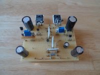
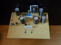
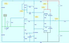
schematic is a little mess, it was some idea that come up, drawn fast before I forgot, I am not a designer but a combiner, is also a profession some tell me🙄... mayb someone here will build and test it.
Attachments

Last edited:
Well, since I posted my last DC version here I've been travelling and doing other stuff.
Anyway when I got back into it I realised that because my present o/p arrangement uses up quite a few volts I had to increase the rails to + & - 34V and that's when the S_ _ _ really hit the Fan.
As soon as I increased the voltage, the parasitic oscillations set it. I can hear Greg laughing . . . . I had to really work at it from several approaches to finally fix it.
Whereas at +&- 25 I somehow needed no gate stoppers ! as soon as I increased the rails, 16Mhz @ about 1V P2P set in.
Anyway to cut a long story short I had to add gate stoppers, rebuild the board with a better layout and finally do the earthing in a very particular way.
Finally after weeks of grappling with it, it's working just fine with 22R gate stoppers @ +&-34V and sounding real nice.
I post pics showing old and new boards my current diagram.
Before I proceed further with this design I will compare it with SSA, another symetrical design of mine & perhaps a folded cascode to see which I prefer.
It seems to me there is a concensus developing that an amp with FB has to be fast to sound good. Which from my ( perhaps small ) understanding means either Current FB or a Folded Cascode . . . . .
It would be great if someone could come up with an amp which had both features in one design . . . . . . . any ideas anyone ?
mike
Current working Diagram
The DC drift is definetly better with the i/p stage CCS fitted.
I think I could adjust it to stay within +&- 50mV ( excluding the 1st 60 seconds )
If I stay with this design I would add a DC servo - it gives more design flexibility.
The DC drift is definetly better with the i/p stage CCS fitted.
I think I could adjust it to stay within +&- 50mV ( excluding the 1st 60 seconds )
If I stay with this design I would add a DC servo - it gives more design flexibility.
Attachments
are the drivers not a little small for the powermosfets, it has need enough current to drive capacitances, I like always 2sj79 and 2sk216 who are good drivers with low capacitance..
Many here are driving O/P devices directly from the VAS with 10-15mA so the VAS is looking at the comparatively high o/p device i/p C - about 500pF in my case.
My VAS is driving into about 40pF which I believe is much lower than the devices you suggest and as has been commented on in this thread several times, lateral mosfets are very easy to drive - bottom line is that there was a perceivable improvement in sound quality when I added the drivers 🙂
mike
Actually I tried the 2sj 2sk devices you mentioned in the middle of my oscillation crisis and things just got worse.
Last edited:
I did mean the zvn into powerfets, it is enough for one pair, and some limited bandwith, have you simulate that?
I like a little current and low impedance for mosfets, but I do most quasy.
Simple is your design, Hugh like that, I wil in future also try that.
happy designing.
I like a little current and low impedance for mosfets, but I do most quasy.
Simple is your design, Hugh like that, I wil in future also try that.
happy designing.
I think Roender's RMI-FC100 would be a great starting design to convert to CFB, in order to achieve a CFB+folded cascode design.
Last edited:
It would be difficult or impossible to do a CFB+FC design because the signal has to be inverted in the VAS. So you would need an extra inverting stage, and that might moot any benefits.
Well, since I posted my last DC version here I've been travelling and doing other stuff.
As soon as I increased the voltage, the parasitic oscillations set it. I can hear Greg laughing . . . . I had to really work at it from several approaches to finally fix it.
mike
Haha, actually no I'm not. I feel your pain, though these days I understand how to deal with oscillation a lot more and it's not so much of a problem.
The problem with this amplifier topology, for me at least, is square wave overshoot. Specifically, correcting it without using an overly large output choke, which does remove a little urgency to the sound.
This is of course asssuming that you care what your square wave performance is like... even with bad overshoot it sounds pretty good!
One good way to get rid of overshoot is to make open-loop gain very low. To many that is not an attractive option.
Nearly every mod I did was to aimed at reducing ringing on square waves - the others were to reduce other types of noise
I tried every measure I could think of to keep the amp's rise time fast & minimising ringing.
Driving from a low impedance - less than 50R - and making the o/p device gate stoppers as small as possible are both useful measures in this regard and a good tight layout helps a lot.
The only other measure which works in theory is a cap across the feedback R this works wonders for rise time vs ringing - but I'm not sure I like the sound of it - I'll check again.
I do love the sound of this amp, when I returned home I was delighted just how good it sounded - but I suspect there may be others that just as good or better 🙂
One good way to get rid of overshoot is to make open-loop gain very low. To many that is not an attractive option.
Yeah, so far I always found I prefer the sound of fast, high feedback amps so long as they are very stable in the critical region.
Yes, you should drop approx 200mV across this resistor.
Quite by chance, I discovered this about 15 years ago working on a cascoded VAS, I was amazed, but could never explain it.
Hugh
Hi Sir
Cascoded VAS, 200mV drop across a resistor in that VAS?
You was amazed, that's interesting.
Can you say more, any drawings?
Thanx
Paul
Mikel, a miller cap or a series feedback cap will decrease overshoot only by decreasing gain at overshoot frequencies; it will only give the appearance of a better behaved amplifier. It does not change the cause of the overshoot which is the resonance at GBP when undercompensated.
I think you should try TMC.
I think you should try TMC.
- Status
- Not open for further replies.
- Home
- Amplifiers
- Solid State
- JFET input, MOSFET VAS, LATERAL output = Perfect!!