This is what I get, Andrew, for example:

http://www.abload.de/img/image13xuzy.png
Best regards - Rudi

http://www.abload.de/img/image13xuzy.png
Best regards - Rudi
BTW. Erno is a really nice guy. I have call him once just to give my credit card details and we had a nice (but short) chat about jfets. Actually he is giving all his knowledge to the public but sometimes you just need to read between the lines...
All the links from 2197 on wards work for me.
Thanks.
Now where can we store all his articles for DIYaudio?
I'll report this via the Moderators. They might have a place for it.
Thanks.
Now where can we store all his articles for DIYaudio?
I'll report this via the Moderators. They might have a place for it.
Hello Andrew
You can PM Jason to ask him a place to store all Boberly's articles in the forum.
Maby we should ask mr Boberly the permission to store all his articles. (I'm sure that he will say yes)
Bye
Gaetan
You can PM Jason to ask him a place to store all Boberly's articles in the forum.
Maby we should ask mr Boberly the permission to store all his articles. (I'm sure that he will say yes)
Bye
Gaetan
Last edited:
I dont know how your squarewave is looking but maybe you could start a new thread as its offtopic here and show some sim results. I wouldnt trust too much in these because of the models but it would be interesting. Sony s top of range amps are using similar setups, asymmetrical though. full Fet designs from input to output and after hearing one of them I must say Im impressed.
I meanwhile figured out what was the exact cause of that shallow slope of the negative going edge, I now tuned it to be symmetrical. A few values changed and can still stay well within the ZVP4464A's dissipation limit. I'll start a thread when I've completed the initial schematic. I'm still experimenting a lot to find out clues on how to improve its various aspects. I'm not just hunting for low THD, but also for decent speeds, stable behaviour into all kinds of loads and yeah, some more THD 😛 By no means the presented schematic is the final one 🙂
I'm not sure if any of the wayback links above worked, but this one brings up the list of articles and the first jfet one opens up fine for me 🙂
Special Articles
Tony.
Special Articles
Tony.
I meanwhile figured out what was the exact cause of that shallow slope of the negative going edge, I now tuned it to be symmetrical. A few values changed and can still stay well within the ZVP4464A's dissipation limit. I'll start a thread when I've completed the initial schematic. I'm still experimenting a lot to find out clues on how to improve its various aspects. I'm not just hunting for low THD, but also for decent speeds, stable behaviour into all kinds of loads and yeah, some more THD 😛 By no means the presented schematic is the final one 🙂
Ill look out for the thread. Also have a look at these 2sj313/2sk2013 😉
Excellence for driving either Mosfet or BJT output stages, for high power good to parrallel.
For me, Fetzilla is off the bench for the moment. It has been replaced by a BJT amp I threw together yesterday. Boy is it nice to be getting faster at this!!!
I will be working on this until further notice.
On another subject, I fried my negative K-multiplier. Once I replaced the faulty diode, I discovered after hours of frustration that the new diode had been marked with the wrong polarity. Shoot, surplus components...
The amp is built from the remains of an Onkyo integrated amp, but I suspect it would have been a nice amp if I had fixed it instead...
- keantoken
Attachments
Would it be considered cheating if I used opamps to create infinite impedance current sources? Because I can tell you, that, a FET and a LED based reference barely impacts THD figures. Mind you, this not need to be an audio opamp, it's task is not to amplify a signal, but to keep a FET sinking the same mA's regardless of drain load.
It should not be hard to design a CCS that has a ridiculously good voltage rejection without resorting to opamps, and it will probably be faster anyways.
If you absolutely need a ridiculous CCS, look up the baxandall cascode.
- keantoken
If you absolutely need a ridiculous CCS, look up the baxandall cascode.
- keantoken
the 2sk216 and 2sj79 is ib full prduction by renasas.com I saw, but still not a model, these mosfets are very interesting..
I have order it now on ebay.
I have order it now on ebay.
Thanks 🙂 I've cooked up the CCS for the VAS now. I can still get sub ppm numbers, but it's a bit of a hit and miss depending on all kinds of things, I attribute it to simulation artifacts at such a level. The over arching average is between 1 and 2 ppm. That's one CCS down without adversely affecting numbers. The VAS itself turned out a little different now. I'ts now driving a cascoded FET as well. The current deciding element in the CCS is... a JFET. These numbers however are now with 200 Watts into 4 Ohms. I know the ECX'es with 2 pairs can handle up to 250W with adequate cooling, but I didn't want to push it and keep them comfortable without creating too much Vgs swing.
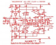
I had simulate the Borbely millennium amp a time ago.
here is the schematic, everything is close to the specs mentioned by borbely, I was curious about it but after I did go on with my own hybrid.
Hi,
Why do you use double cascode in the IPS? I would go for JFET-MOSFET cascode and no JFET-JFET-MOSFET. First of all it will be almost not possible to source proper SK170/SJ74 with required Vgs. If you want to keep this kind of cascode better switch to sk246/sj103 or soemthing from 2nxxxx eg. 2n2457/2n2462 afair. I am planing to build something like this soon.
Today I was listening fetzilla with pair of 10 000EUR+ speakers... this is really high end amplifier!
That's nice to hear, Barmanekm!!
Simple, too, no cascodes as you rightly point out.......
Hugh
Simple, too, no cascodes as you rightly point out.......
Hugh
Hi,
Why do you use double cascode in the IPS? I would go for JFET-MOSFET cascode and no JFET-JFET-MOSFET. First of all it will be almost not possible to source proper SK170/SJ74 with required Vgs. If you want to keep this kind of cascode better switch to sk246/sj103 or soemthing from 2nxxxx eg. 2n2457/2n2462 afair. I am planing to build something like this soon.
Today I was listening fetzilla with pair of 10 000EUR+ speakers... this is really high end amplifier!
The schematic is a real Borbely design,, the j fets was what I had in sim to test it, the cascode is because of the high dc supply of the amp, Borbely has reasons to to it like this way I presume.
Ik have made a hybrid, and listen to it now, so beautifull the music it produces, so mu warmth and deep strong bass even if you play loud. but I go test the others also fetzilla but have not much time now, working on a motorhome.
Please find Millenium documentation attached:
There is simple cascode
Great to hear that you have build it. Waiting for more feedback 🙂
There is simple cascode
Great to hear that you have build it. Waiting for more feedback 🙂
Attachments
Last edited:
Please find Millenium documentation attached:
There is simple cascode
Great to hear that you have build it. Waiting for more feedback 🙂
I have not build it yet, but simulate, the reason Borbely did double the fets was because of a lower input capacity, so I think that make it single like yours have not much impact if the source can drive low impedance.
This one I have done with the idea high supply voltage and more power with low distortion, with 20 khz sinus om 140 watt 4 ohm it gives 0.035 THD in simulation.
It is complete balanced so matching is needed, I have this design already here on forum but this is a little changed in the meantime.
Attachments
That's nice to hear, Barmanekm!!
Simple, too, no cascodes as you rightly point out.......
Hugh
What's "wrong" with cascodes? I think they are a great building block to allow working with higher voltages and offload loads from gain/current control devices.
In my latest design (initial design posted in this thread) I've integrated a "tracking cascode" into the VAS that adds a lot more linearity than a fixed point cascode would. As a result I can use a reasonable VAS current over a large voltage range. The corresponding current source for the VAS is also cascoded, though this one is a fixed point cascode which is fine since the current source doesn't handle a moving signal.
Altogether, this configuration allowed the design to keep sub ppm numbers.
Last edited:
I think Hugh's comment here might be that sub ppm designs don't necessarily sound good.
My comment would be if you have used these circuit elements in your designs before and liked what you heard after you added them then it shouldn't really matter to you what others think about them.
I came to this thread with some fixed ideas about what I did & didn't like. Along the way some of those ideas got blown away by simply trying different things and listening. Hugh's and my versions of the design discussed in this thread came out quite different, but both of them where based on trying ideas & listening to see what was preferred.
Your design might sound great but sub ppm HD would not be my highest priority.
mike
- Status
- Not open for further replies.
- Home
- Amplifiers
- Solid State
- JFET input, MOSFET VAS, LATERAL output = Perfect!!