As I understand it, becuase in amps with feedback, the whole operation of the circuit is strongly dependant on the operation of the F/B device(s), if this device is changing temperature due to power variations across it caused by the signal then the resultant heating and cooling effects are amplified along with the signal and have a disproportionally high effect in the final performance on an amp.
Almost impossible to assess in spice but one hears that addressing this issue removes a kind of smearing effect on the sound.
that's why I was hoping someone here had done an A/B comparison 🙂
I built this feature into my last amp but did not do an A/B 🙁
Almost impossible to assess in spice but one hears that addressing this issue removes a kind of smearing effect on the sound.
that's why I was hoping someone here had done an A/B comparison 🙂
I built this feature into my last amp but did not do an A/B 🙁
AKSALineup, SW,
It's looking good. Anything which has H2 at -83dB and H5 at -123dB gets my vote; that would sound marvellous, very clear.
However, I wouldn't use a zener to set the cascode voltage. I'd be inclined to go back to the resistor divider, and add a 47uF cap between cascode base and ground.
The design is excellent, but will require careful selection of jfet since the gm of this device contributes hugely to loop gain, which should be prescribed to fix the lag compensation at 22pF, assuming that is your optimum dimension.
The most important aspect is that both jfets are the same and therefore you finish with very similar CCS calibrations for zero output offset.
Aside from that, you could add a bootstrap in place of the VAS CCS, which will increase H2 and H3, both musical, but nothing more to add. Very nice circuit, build and listen!
I really like FETzilla, a corruption of James Bongiorno's excellent circuit of 1974 at SAE, the Ampzilla, which became a template for some of the world's best amplifiers.
Cheers,
Hugh
As a matter of fact I have already gone back from zener to a divider 4.7k/4.7k with an electrolyt 47uF.
Me too, do not want to add zener noise into the circuit.
Or have to counteract such noise.
Bootstrap is an option. It is in line with keeping the amplifier simple.
I will try and see. swordfishy has already tried it in sim.
Okay, Fetzilla, like metal suggested will be the name.
Hugh has mentioned the possible use of a bootstrap circuit for the VAS - similar to the one attached. He has been doing this a long time and I respect his thoughts and design ideologies.
It simulates at twice the distortion (but still very very low) but it offers a few benefits:
1) The extra distortion is of the nice low order variety so it would sound nice.
2) Two less active devices to worry about.
3) Reduced chance of oscillation problems.
Having built a JLH with a bootstrapped VAS, I can confirm these claims about simpler circuits sounding good.
Anyway, I'm not saying we have to choose one or the other at this point but it's an interesting and elegant option for the circuit.
I like the idea of bootstrap.
And Hugh says it could have influence on the harmonics in a good way.
I see you have already tested it in sim.
Hawksford cascode.Does a regular cascode sound as good as a well implemented "hawksford" cascode ( where the voltage across the i/p device is held constant even when the signal is applied ).
To me, logically the hawksford cascode is purer and I have used it but I never did a listening comparison.
It could certainly be an option. If Hugh is positive it can be addded.
My approach is otherwise to keep things simple.
Actually I prefer to go without any cascode.
This is possible with 2SK170 as in my original circuit.
danspyLinesonic fet #1
how abut 2SK30ATM for Input?
Because dis is the only wan i can get hold of.
2SK30ATM Datasheet pdf - Field Effect Transistor Silicon N Channel Junction Type Low Noise Pre-Amplifier, Tone Control Amplifier and DC-AC High Input Impedance Amplifier Circuit Applications - TOSHIBA
Sure we, you can try other JFETs.
I shall try to get a hold of 2SK30 spice model.
And see what sdata we can expect.
I see no trouble with using another FET. 2SK246 should work.
Dank you Lineup
I donut no if dis is a spice model but maybe it helps.
.model J2SK30atm NJF(beta=.768m vto=-2.70 cgd=2.6p cgs=8.2p dev 10% LOT 60%)
* CQ 1988/7
I donut no if dis is a spice model but maybe it helps.
.model J2SK30atm NJF(beta=.768m vto=-2.70 cgd=2.6p cgs=8.2p dev 10% LOT 60%)
* CQ 1988/7
danspy
it is a model for spice
but it look suspicious
I will try to make it work
EDIT: it looks like the 2SK30ATM spice model can work
I have it in circuit now
danspy, what output devices do you think of?
it is a model for spice
but it look suspicious
I will try to make it work
EDIT: it looks like the 2SK30ATM spice model can work
I have it in circuit now
danspy, what output devices do you think of?
Last edited:
Hire is a bigger wan.
*2SK30
*id(R 0.3-0.75 / O 0.6-1.4 / Y 1.2-3.00 / GR 2.6-6.5)
.model J2SK30r NJF(vto=-0.8v beta=0.75m lambda=0 cgd=2.6p cgs=8.2p
+ dev 10% LOT 60%)
.model J2SK30o NJF(vto=-1.1v beta=0.75m lambda=0 cgd=2.6p cgs=8.2p
+ dev 10% LOT 60%)
.model J2SK30y NJF(vto=-1.8v beta=0.75m lambda=0 cgd=2.6p cgs=8.2p
+ dev 10% LOT 60%)
.model J2SK30gr NJF(vto=-2.8v beta=0.75m lambda=0 cgd=2.6p cgs=8.2p
+ dev 10% LOT 60%)
.model J2SK30atm NJF(beta=.768m vto=-2.70 cgd=2.6p cgs=8.2p dev 10% LOT 60%)
* CQ 1988/7
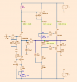
Here is a danspy 2SK30ATM version of FetZilla
2SK30ATM gives a little more distortion than 2SK170.
But still rather low dist at 1 Watt: THD 0.015%
It will work good.
I have added bootstrap with capacitor 47uF
I use output 2SK1058/2SJ162 as in original circuit.
2SK30ATM gives a little more distortion than 2SK170.
But still rather low dist at 1 Watt: THD 0.015%
It will work good.
I have added bootstrap with capacitor 47uF
I use output 2SK1058/2SJ162 as in original circuit.
Attachments
Perfect now i need only the IRF610, i have only 2 IRF640.
But the rest i need i have already 40 2SK30ATM and 8 2SK1058/2SJ162, and i love the Sound of Bootstrap.
But the rest i need i have already 40 2SK30ATM and 8 2SK1058/2SJ162, and i love the Sound of Bootstrap.
Will you now use the jfet current to adjust to 0.V..??
better to set the current and then pull the top to low offset..
better to set the current and then pull the top to low offset..
Last edited:
Lineup,
I like the look of that circuit with the bootstrap VAS!
If this circuit makes less than 1% distortion at 20kHz and 10W in real life I'll be very happy.
Have you noticed with these circuits when simming them that the distortion does not seem to change much between 1W and 20W? This is what I am finding and it is the first amplifier I have simulated and had such a result.
Something I like to do is sim the THD at 20kHz too, as this is when we really start to see the effect of the fet gate capacitance come in to play, and in fact sometime more current in the input and VAS stages may create more distortion at 1kHz but cause significant improvement at 20kHz. I wonder what will prove to be the best compromise?
How did you arrive at 47uF for the bootstrap capacitor? Did you try any other values?
Thanks again, I am enjoying seeing this progress.
Last edited:
Hugh,
Still interested, just waiting on parts unfortunately. As soon as they arrive it's back on! I just wish I had ordered more laterals (only got 10 of each)!
Been trying some alternative circuits too which I will post tonight or tomorrow. Think I have found a good compromise between complexity and performance.

Ahhh, you're going to beat me to it! What is that awesome cad package you're using?
Seeing it laid out like that really illustrates just how simple the circuit is.
Hugh, do you think the lateral fets sold by jaycar are genuine hitachi? If so I might collect some tomorrow and build an incarnation of lineup's circuit with the J201/202/203s I have lying around while I wait for the 2sk170s. Only problem is they aren't great devices, though they are made for audio use and do have a reasonable dissipation rating.
Last edited:
- Status
- Not open for further replies.
- Home
- Amplifiers
- Solid State
- JFET input, MOSFET VAS, LATERAL output = Perfect!!