HI Lineup,
Thanks for the thoughtful post.
When you vary the gate/source resistor on the VAS to achieve zero output offset, you are altering the current through the jfet. As you change the stage current of the input stage, you in fact change the loop gain, which in turn requires a retune of the lag compensation cap between drain and gate of the VAS. This cap is pivotal to stability, and in fact, to sound quality.
The gate of a jfet is a fragile rose, and easily punched through. Any slow moving DC spike at the input could damage it. Solution: Use a zener to ground, and use a blocking cap to block any DC voltage.
It really is no problem to bias the input gate to a small positive voltage. I do it all the time on my Soraya, Maya and NAKSA amps. And it does not change the gm of the input stage!
Hugh
What do you think of my latest circuit?
You really think I should put a zener from gate of 2SK170?
I have seen many circuits without it.
DC blocking cap is my standard at the input.
Lineup,
That looks terrific..... I would not do it exactly the same way, preferring to return stage current for U2 via R5, but this would work very well and gets around the offset drift and adjustment issues.
Now, here's hoping it's quickly built and auditioned. Should sound very good. Do you have a spectrum of the distortion artefacts at 1KHz and 20KHz, referenced to +20dBU (around 14.5Vp into 8R)?
Hugh
Now, here's hoping it's quickly built and auditioned. Should sound very good. Do you have a spectrum of the distortion artefacts at 1KHz and 20KHz, referenced to +20dBU (around 14.5Vp into 8R)?
Hugh
It turned out that +20dBU is like 13 Watt RMS into 8Ohm.
I have a Wattmeter in my circuit.
Note: The circuit runs in Class A, biased 1.40A.
Because swordfishy wants a Class A amplifier.
The circuit can absolutely run in Class AB with no bigger difference, I think.
Harmonics shows 2nd order and 3rd order are dominant
At +20dBU 1kHz is THD 0.006%
At +20dBU 20kHz is THD 0.022%
See diagram 1 for 1 kHz
See diagram 2 for 20 kHz
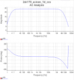
AC Analysis.
-3dB at above 4MHz.
Think we need an input filter ....
Attachments


Last edited:
Lineup, Hugh,
Thanks again. So lineup does this mean that you also prefer the cascoded input stage now? Would it be worth locking the cascode voltage with a zener? The new circuit looks good. With the cascode we can use higher currents and maybe even a bjt vas if that sims better. The bd140 would be nice as it can safely dissipate half a watt with no heatsink so we could up the vas current to 20mA easily. But we can stick with the zvp3310a for now - it's a great little device.
No need to be nervous - this is the fun part!
There's been a delay with my 2SK170s. Unfortunately they couldn't complete my order for 50 parts, they only have 26 in stock - I guess the website was lying as it said they had thousands in stock. Anyway, it's only a short term delay I hope, and if all else fails I can just take what they have. I ordered both Idss types so we can experiment with input stage currents. Also ordered a bunch of bc550/560cs and bd139/140-16s to play with! I already have a bunch of the zvp3310as here.
Last edited:
In a real circuit, with some ripple on the rails, perhaps a 10/12 volt zener is good.
2SK170. If there are BL to buy so buy them. BL can be run at lower currents, too.
It is just a matter of source resistor or current source.
ZVP3310a makes it a little bit better in my tests. Better than IRF9610 which is one other option.
With BD140 I think it might do as well as ZVP3310.
I have yet to see if higher VAS current does better with Exicon.
I do not think so
But with HEXFET IRFP240/9240 it is better with higher current.
What do you think of the solution with current source to 2SK170?
If you like you can start without it. Just connect the two resistors to set gain.
And let us see how stable it is as the original circuit.
If it drift and you get offset, then you add current source.
You really plan to run it in Class A?
It is 70 Watt to dissipate. You need a good heatsink!
-------------
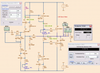
The latest circuit with input filter 1k+220p.
And output Zobel 100n+10R. And Zener 12V.
Highest output in 8 Ohm before distortion rise is 25.9 Watt
See schematic.
2SK170. If there are BL to buy so buy them. BL can be run at lower currents, too.
It is just a matter of source resistor or current source.
ZVP3310a makes it a little bit better in my tests. Better than IRF9610 which is one other option.
With BD140 I think it might do as well as ZVP3310.
I have yet to see if higher VAS current does better with Exicon.
I do not think so
But with HEXFET IRFP240/9240 it is better with higher current.
What do you think of the solution with current source to 2SK170?
If you like you can start without it. Just connect the two resistors to set gain.
And let us see how stable it is as the original circuit.
If it drift and you get offset, then you add current source.
You really plan to run it in Class A?
It is 70 Watt to dissipate. You need a good heatsink!
-------------
The latest circuit with input filter 1k+220p.
And output Zobel 100n+10R. And Zener 12V.
Highest output in 8 Ohm before distortion rise is 25.9 Watt
See schematic.
Attachments
Lineup,
Looks good. Thank you. The only addition I would make is to put a 10k resistor and 47u cap across the Zener to reduce noise and maybe a cap across the bias resistor. No need to change the schematic though - you must be sick of simulating! I will try to get microsim so we can share models more easily.
I think the ccs version is the one to build as it will be a little bit more controllable and predictable.
The 3310 is very good but the 9610 in recent years has changed and now has a significant non linearity. Nelson Pass has mentioned it somewhere - I will try to find the post for you. So if we ever want more current we may need to find a nicer device.
I think you are right though, the laterals don't need much current, which is good. Do you think we should add a gate capacitor to the n channel fet to balance the gate capacitance? - like here:
Project 101 - High Power, High Fidelity MOSFET power amplifier
I tried simming with a gate capacitor but it made no difference.
You are right, it sims better with the fet ccs in the vas. I only hope that when it comes to building the circuit that the ccs doesn't oscillate. In real life circuits I have found fet CCS's to be more unstable, requiring resistors to slow them down, which removes the speed advantage over a bjt design.
I also simmed the cascode input and having the cascode does add quite a bit of distortion, but I think it will be for the best in practice. Though maybe with the ccs in the input stage it's no longer necessary? Anyway, these are some things I can fiddle with in the final design.
I think I will run highly biased class ab, with maybe 1 amp of current for 25 watts of dissipation per device. But if listening tests show that a lower bias works as well I will be happy to use that too. Don't worry I have big heatsinks.
I think the final design is going to have a very critical pcb layout with the CCS's the way they are with no resistors to slow them down. Might need a gate stopper on the 3310s too.
Anyway, thank you for all of your help so far. This has been very interesting and I hope you are enjoying it too.
Greg.
Last edited:
swordfishy
You know more than me about some things.
You are no beginner. Or you have read a lot.
How do I calculate a gate capacitor?
It is possibly a difference between N and P from the datasheet.
Is it Cin?
And what is the ideal value on Gate stoppers for Exicon?
220 Ohm is just an estimate value.
Yes, one cap across the zener would be good.
There is almost no difference I can find between Class AB and Class A.
I would run it 100mA Class AB.
I do not think it is necessary with Gate stopper for VAS transistor.
And no source resistor for ZVP3310 or IRF9610.
But you will see. I may be wrong.
Cascode does not add much distortion.
I think it is a good thing to keep it.
PCB layout is important. Yes. Otherwise the JFET and MOSFET will start to oscillate the circuit.
WE should put a name on this amplifier.
I see most other amplifiers have names. Names to use like 'DX', 'Mongrel AX', 'Symasym'.
After all there are plenty of different FETs in amp.
How about 'Fetisch'
Or 'Fetomantic'
Or 'Fetom'
Or 'Fetty Boop'
I see most other amplifiers have names. Names to use like 'DX', 'Mongrel AX', 'Symasym'.
After all there are plenty of different FETs in amp.
How about 'Fetisch'
Or 'Fetomantic'
Or 'Fetom'
Or 'Fetty Boop'
Lineup, SW,
It's looking good. Anything which has H2 at -83dB and H5 at -123dB gets my vote; that would sound marvellous, very clear.
However, I wouldn't use a zener to set the cascode voltage. I'd be inclined to go back to the resistor divider, and add a 47uF cap between cascode base and ground.
The design is excellent, but will require careful selection of jfet since the gm of this device contributes hugely to loop gain, which should be prescribed to fix the lag compensation at 22pF, assuming that is your optimum dimension.
The most important aspect is that both jfets are the same and therefore you finish with very similar CCS calibrations for zero output offset.
Aside from that, you could add a bootstrap in place of the VAS CCS, which will increase H2 and H3, both musical, but nothing more to add. Very nice circuit, build and listen!
I really like FETzilla, a corruption of James Bongiorno's excellent circuit of 1974 at SAE, the Ampzilla, which became a template for some of the world's best amplifiers.
Cheers,
Hugh
Fetus haha. I like it. FET LineUp Swordfishy amplifier. Sounds a bit wrong though 🙂
It's nice to hear someone say that, but I am actually quite new to all of this. I think you have been doing this a lot longer and know a lot more than me. But I'm learning fast and have built quite a few amplifiers for the time I have been interested in them 🙂 Some of my theory is still quite weak but I'm just throwing in my 2c wherever I can apply some practical experience.
As for the gate capacitor on the n channel lateral, yes I think your idea of using the difference between the capacitances on the datasheet would be a good start. I tried simming with 200pf and it made no difference, but Rod Elliot's amp is apparently unstable without it.
This is one benefit to using class A - no switch on or off, so reduced chance of gate oscillation. So maybe no need to worry about this unless you want to run AB.
The other option is to use assymetrical gate resistors which may be a more elegant and less troublesome solution (use a larger resistor for the N channel device).
Regarding gate resistors - Nelson uses 221R, and I am sure he has fiddled with this value for many years so that seems like a good start. In any case I can't see 100R either side of 220R making a substantial difference to the performance at typical audio frequencies. I might fiddle with this a bit in the actual circuit - pcb layout, etc will be what determines the minimum value.
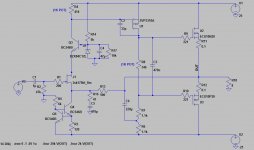
Hugh has mentioned the possible use of a bootstrap circuit for the VAS - similar to the one attached. He has been doing this a long time and I respect his thoughts and design ideologies.
It simulates at twice the distortion (but still very very low) but it offers a few benefits:
1) The extra distortion is of the nice low order variety so it would sound nice.
2) Two less active devices to worry about.
3) Reduced chance of oscillation problems.
Having built a JLH with a bootstrapped VAS, I can confirm these claims about simpler circuits sounding good.
Anyway, I'm not saying we have to choose one or the other at this point but it's an interesting and elegant option for the circuit.
You know more than me about some things. You are no beginner. Or you have read a lot.
It's nice to hear someone say that, but I am actually quite new to all of this. I think you have been doing this a lot longer and know a lot more than me. But I'm learning fast and have built quite a few amplifiers for the time I have been interested in them 🙂 Some of my theory is still quite weak but I'm just throwing in my 2c wherever I can apply some practical experience.
As for the gate capacitor on the n channel lateral, yes I think your idea of using the difference between the capacitances on the datasheet would be a good start. I tried simming with 200pf and it made no difference, but Rod Elliot's amp is apparently unstable without it.
This is one benefit to using class A - no switch on or off, so reduced chance of gate oscillation. So maybe no need to worry about this unless you want to run AB.
The other option is to use assymetrical gate resistors which may be a more elegant and less troublesome solution (use a larger resistor for the N channel device).
Regarding gate resistors - Nelson uses 221R, and I am sure he has fiddled with this value for many years so that seems like a good start. In any case I can't see 100R either side of 220R making a substantial difference to the performance at typical audio frequencies. I might fiddle with this a bit in the actual circuit - pcb layout, etc will be what determines the minimum value.
Hugh has mentioned the possible use of a bootstrap circuit for the VAS - similar to the one attached. He has been doing this a long time and I respect his thoughts and design ideologies.
It simulates at twice the distortion (but still very very low) but it offers a few benefits:
1) The extra distortion is of the nice low order variety so it would sound nice.
2) Two less active devices to worry about.
3) Reduced chance of oscillation problems.
Having built a JLH with a bootstrapped VAS, I can confirm these claims about simpler circuits sounding good.
Anyway, I'm not saying we have to choose one or the other at this point but it's an interesting and elegant option for the circuit.
Attachments
Last edited:
Linesonic fet #1
how abut 2SK30ATM for Input?
Because dis is the only wan i can get hold of.
2SK30ATM Datasheet pdf - Field Effect Transistor Silicon N Channel Junction Type Low Noise Pre-Amplifier, Tone Control Amplifier and DC-AC High Input Impedance Amplifier Circuit Applications - TOSHIBA
how abut 2SK30ATM for Input?
Because dis is the only wan i can get hold of.
2SK30ATM Datasheet pdf - Field Effect Transistor Silicon N Channel Junction Type Low Noise Pre-Amplifier, Tone Control Amplifier and DC-AC High Input Impedance Amplifier Circuit Applications - TOSHIBA
Does a regular cascode sound as good as a well implemented "hawksford" cascode ( where the voltage across the i/p device is held constant even when the signal is applied ).
To me, logically the hawksford cascode is purer and I have used it but I never did a listening comparison.
To me, logically the hawksford cascode is purer and I have used it but I never did a listening comparison.
Good point Mike, and here, it really wouldn't be difficult to check in simulation.
I'll get back to you.....
Hugh
I'll get back to you.....
Hugh
Thanks Hugh,
But as I understand it the effects of the target of this idea i.e. constant power across a device, even during in the presence of a signal, are not really possible to evaluate in spice.
I have checked that constant power is achieved in spice in other designs but I think this one would have to be assessed aurally.
But I look forward to hear what you find to make sure that this idea does not mess things up in other respects.
cheers
mike
Hawksford Cascode, with 1mA CCS feeding 1K resistor between base of cascoding 2N5210 and source of jfet:
Harmonic Frequency Fourier Normalized Phase Normalized
Number [Hz] Component Component [degree] Phase [deg]
1 1.000e+03 1.373e+01 1.000e+00 0.71° 0.00°
2 2.000e+03 1.037e-03 7.556e-05 160.45° 159.73°
3 3.000e+03 2.952e-04 2.150e-05 17.91° 17.20°
4 4.000e+03 4.871e-04 3.549e-05 170.67° 169.96°
5 5.000e+03 4.214e-04 3.070e-05 -178.90° -179.61°
6 6.000e+03 3.185e-04 2.320e-05 -178.65° -179.36°
7 7.000e+03 2.706e-04 1.972e-05 179.96° 179.25°
8 8.000e+03 2.391e-04 1.741e-05 179.95° 179.24°
9 9.000e+03 2.127e-04 1.549e-05 -179.89° -180.61°
Total Harmonic Distortion: 0.009922%
And standard, as in Post #154:
Harmonic Frequency Fourier Normalized Phase Normalized
Number [Hz] Component Component [degree] Phase [deg]
1 1.000e+03 1.373e+01 1.000e+00 0.71° 0.00°
2 2.000e+03 1.127e-03 8.213e-05 151.59° 150.87°
3 3.000e+03 2.532e-04 1.845e-05 20.29° 19.57°
4 4.000e+03 4.841e-04 3.527e-05 172.11° 171.40°
5 5.000e+03 4.177e-04 3.043e-05 -178.94° -179.66°
6 6.000e+03 3.189e-04 2.324e-05 -178.86° -179.58°
7 7.000e+03 2.712e-04 1.976e-05 179.97° 179.26°
8 8.000e+03 2.392e-04 1.743e-05 179.98° 179.27°
9 9.000e+03 2.128e-04 1.550e-05 -179.90° -180.61°
Total Harmonic Distortion: 0.010359%
Conclusions?
It's clear to me that you are right; a listening test, switchable, would be preferred here. On the face of it, MOH (Malcolm Omar Hawksford) cascode would have lower distortion, but only for H2, which is not that important and arguably might even improve musicality by 'warming' up the sound.
Hugh
Harmonic Frequency Fourier Normalized Phase Normalized
Number [Hz] Component Component [degree] Phase [deg]
1 1.000e+03 1.373e+01 1.000e+00 0.71° 0.00°
2 2.000e+03 1.037e-03 7.556e-05 160.45° 159.73°
3 3.000e+03 2.952e-04 2.150e-05 17.91° 17.20°
4 4.000e+03 4.871e-04 3.549e-05 170.67° 169.96°
5 5.000e+03 4.214e-04 3.070e-05 -178.90° -179.61°
6 6.000e+03 3.185e-04 2.320e-05 -178.65° -179.36°
7 7.000e+03 2.706e-04 1.972e-05 179.96° 179.25°
8 8.000e+03 2.391e-04 1.741e-05 179.95° 179.24°
9 9.000e+03 2.127e-04 1.549e-05 -179.89° -180.61°
Total Harmonic Distortion: 0.009922%
And standard, as in Post #154:
Harmonic Frequency Fourier Normalized Phase Normalized
Number [Hz] Component Component [degree] Phase [deg]
1 1.000e+03 1.373e+01 1.000e+00 0.71° 0.00°
2 2.000e+03 1.127e-03 8.213e-05 151.59° 150.87°
3 3.000e+03 2.532e-04 1.845e-05 20.29° 19.57°
4 4.000e+03 4.841e-04 3.527e-05 172.11° 171.40°
5 5.000e+03 4.177e-04 3.043e-05 -178.94° -179.66°
6 6.000e+03 3.189e-04 2.324e-05 -178.86° -179.58°
7 7.000e+03 2.712e-04 1.976e-05 179.97° 179.26°
8 8.000e+03 2.392e-04 1.743e-05 179.98° 179.27°
9 9.000e+03 2.128e-04 1.550e-05 -179.90° -180.61°
Total Harmonic Distortion: 0.010359%
Conclusions?
It's clear to me that you are right; a listening test, switchable, would be preferred here. On the face of it, MOH (Malcolm Omar Hawksford) cascode would have lower distortion, but only for H2, which is not that important and arguably might even improve musicality by 'warming' up the sound.
Hugh
Last edited:
- Status
- Not open for further replies.
- Home
- Amplifiers
- Solid State
- JFET input, MOSFET VAS, LATERAL output = Perfect!!