Well, this is amazing......
FET has more OLG, wow!
Mike, is your graph a Bode plot, that is, does it reveal how much phase margin we have at unity loop gain? It looks like about 160 degrees, which is remarkable!
Your use of phase lead - John Linsley Hood's technique and one I use in all my amps - works brilliantly and in some cases means you can eschew lag compensation completely.
It's value is influenced strongly by the shunt fb resistor, your values sound good.
If you use 470R of VAS degen, this will greatly increase output impedance of the voltage amp, but it should be OK if you are driving low cap lateral fets.
I had expected a jfet VAS would have less, not more, loop gain. This comes as a surprise to me. One way of reducing loop gain would be to use a bootstrap on the VAS, because the current variation it introduces should exploit the lower transconductance of the jfet, making the input stage work a bit harder.
Very interesting work SWF!
Hugh
Dear Swordfishy,
try VAS Fet with no gate resistor and a degenerating Source one? 10-50ohms should do...
Best
DocO
try VAS Fet with no gate resistor and a degenerating Source one? 10-50ohms should do...
Best
DocO
Phew! So many replies. OK, one at a time:
Yeah this sounds good. Will give it a go tonight.
No not at all 🙂
I did try this on my previous circuit with the FET VAS and it did not appear to help. However I tried much larger values (150 - 330pF), so I will try something smaller.
Haha, now you know what I am dealing with. This thing is a beast. I can put 5 ohms across the output and get rail to rail oscillations way up in the mHz range. It's really quite amazing.
What do you mean by "the signatures are different"? Are you referring to the distortion signature? If so, then you are simulating what I am hearing I think. The BJT version sims with higher H2 and it certainly sounds that way. It is very relaxed and nice sounding. Vocals come to life and separate from the instruments. The FET version is a bit more in your face. It has limitless bandwidth and it sounds that way. Very fast transients and no problem doing anything the source asks. BTW, what current are you running in the BD140 for your simulation?
As I have said before, those people who want a tube/valve sound would do better with the BJT version - which is by no means slow anyway, and makes a dead perfect 20kHz square wave with far less ringing than the fet version. Even the 100kHz wave isn't too bad as I posted earlier.
The question is, what sound do you like and do want bandwidth at radio frequencies?? 🙂 🙂
This layout, with the SE fet input, SE VAS and PP fet output is a fantastically flexible topology and I think any person could find a sound to their tastes just by changing the VAS device. It's really good fun.
Thanks Hugh. Glad you're enjoying it. It's a fun process.
These results are as I thought. I just knew the damn thing would oscillate again as soon as I got rid of the BJT. However, after managing to tame it last time I think I know what I need to do now. It's going to be very interesting.
DocO, I was just thinking this myself. Maybe the gate resistor is introducing lag. Will get rid of it tonight.
It already has 50R of source degeneration....
perhaps try 100 or 200pF in series with the value of your feedback resistor, from the VAS stage to the source of the i/p FET - I found that this was the best compensation method available in spice - no miller cap
Yeah this sounds good. Will give it a go tonight.
Are you sure your input filter with C2 from post #336 circuit is really effective....
No not at all 🙂
Also, with laterals like 2sk1058/j162 I always put a 33pf cap between the drain and gate of the N mosfet to prevent oscillation...
I did try this on my previous circuit with the FET VAS and it did not appear to help. However I tried much larger values (150 - 330pF), so I will try something smaller.
.....and the signatures are hugely different.
......So it is now easy for me understand why the two versions sound so different and why the Mosfet needs compensation . . .
Haha, now you know what I am dealing with. This thing is a beast. I can put 5 ohms across the output and get rail to rail oscillations way up in the mHz range. It's really quite amazing.
What do you mean by "the signatures are different"? Are you referring to the distortion signature? If so, then you are simulating what I am hearing I think. The BJT version sims with higher H2 and it certainly sounds that way. It is very relaxed and nice sounding. Vocals come to life and separate from the instruments. The FET version is a bit more in your face. It has limitless bandwidth and it sounds that way. Very fast transients and no problem doing anything the source asks. BTW, what current are you running in the BD140 for your simulation?
As I have said before, those people who want a tube/valve sound would do better with the BJT version - which is by no means slow anyway, and makes a dead perfect 20kHz square wave with far less ringing than the fet version. Even the 100kHz wave isn't too bad as I posted earlier.
The question is, what sound do you like and do want bandwidth at radio frequencies?? 🙂 🙂
This layout, with the SE fet input, SE VAS and PP fet output is a fantastically flexible topology and I think any person could find a sound to their tastes just by changing the VAS device. It's really good fun.
FET has more OLG, wow!
Your use of phase lead - John Linsley Hood's technique and one I use in all my amps - works brilliantly and in some cases means you can eschew lag compensation completely.
It's value is influenced strongly by the shunt fb resistor, your values sound good.
I had expected a jfet VAS would have less, not more, loop gain. This comes as a surprise to me. One way of reducing loop gain would be to use a bootstrap on the VAS, because the current variation it introduces should exploit the lower transconductance of the jfet, making the input stage work a bit harder.
Very interesting work SWF!
Thanks Hugh. Glad you're enjoying it. It's a fun process.
These results are as I thought. I just knew the damn thing would oscillate again as soon as I got rid of the BJT. However, after managing to tame it last time I think I know what I need to do now. It's going to be very interesting.
Dear Swordfishy,
try VAS Fet with no gate resistor and a degenerating Source one? 10-50ohms should do...
Best
DocO, I was just thinking this myself. Maybe the gate resistor is introducing lag. Will get rid of it tonight.
It already has 50R of source degeneration....
I do think that the BJT version is the best...and most flexible... solution.. there you can also run more current at get a firmer drive of the laterals...10-15 mA.
I like the performance of a cascodede jfet at the input...which makes the whole circuit scalable to higher rails..
I believe that the app 100 mV drift the you get here is perfectly all right.
I like the performance of a cascodede jfet at the input...which makes the whole circuit scalable to higher rails..
I believe that the app 100 mV drift the you get here is perfectly all right.
I do think that the BJT version is the best...and most flexible... solution.. there you can also run more current at get a firmer drive of the laterals...10-15 mA.
I like the performance of a cascodede jfet at the input...which makes the whole circuit scalable to higher rails..
I believe that the app 100 mV drift the you get here is perfectly all right.
Yes, I'm running 16mA currently and it's quite good. I'm happy without the cascode. I genuinely don't need more than 25v rails. I have scoped my speakers and it turns out I seldom need more than a few watts.
Have you seen the latest DC offset plot in post #340? The offset sits nicely at 15mV within a few minutes of warming up. Setting the offset from the input gate has worked wonders (thanks Hugh).
Last edited:
Well, this is amazing......
FET has more OLG, wow!
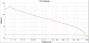
Mike, is your graph a Bode plot, that is, does it reveal how much phase margin we have at unity loop gain? It looks like about 160 degrees, which is remarkable!
it's not a bode just open loop gain - I inserted a huge spice inductor to eliminate all AC FB, took out all filters etc and measured levels at i/p & o/p - multisim normalises the result i.e. assigns 0db to i/p signal
Your use of phase lead - John Linsley Hood's technique and one I use in all my amps - works brilliantly and in some cases means you can eschew lag compensation completely. It's value is influenced strongly by the shunt fb resistor, your values sound good.
much of my early audio electronics knowledge came from pouring over JLH articles & designs until I really understood them - it took a long time !
If you use 470R of VAS degen, this will greatly increase output impedance of the voltage amp, but it should be OK if you are driving low cap lateral fets.
I only did this as an experiment to see what it took to even playing field, 10mA in the VAS gives a 4.7V drop across 470 and this seems a bit too much
I had expected a jfet VAS would have less, not more, loop gain. This comes as a surprise to me. One way of reducing loop gain would be to use a bootstrap on the VAS, because the current variation it introduces should exploit the lower transconductance of the jfet, making the input stage work a bit harder.
I think the BJT has less OLG in at audio frequencies simply because it draws current from the i/p stage - this can be imitated by putting a 470K resitor in the "miller" position across the 4424 ( this gives ruler flat OLG of about 80db up to about 100Khz, not sure if this is desirable or sounds good - I did it to help understand the differences between BJT & FET VAS but I thought even, controllable gain across entire audio band might be desirable ) based on my & others experience here on JLH simple class A, I'm not keen about bootstraps. Most agreed that a CCS sounded better and I suspect one reason for this is that a CCS eliminates more PSU noise and for me that is a major prerequisite for a pleasant & natural sound.
As Swordfishy says how much gain / detail we prefer is just a preference about what sound you like - detailed or mellow . . . but a well implemented high feedback amp can also seriously reduce PSU noise, so choices may depend also upon PSU design as well - which is another topic completely !
Last edited:
What do you mean by "the signatures are different"? Are you referring to the distortion signature? If so, then you are simulating what I am hearing I think. The BJT version sims with higher H2 and it certainly sounds that way. It is very relaxed and nice sounding. Vocals come to life and separate from the instruments. The FET version is a bit more in your face. It has limitless bandwidth and it sounds that way. Very fast transients and no problem doing anything the source asks. BTW, what current are you running in the BD140 for your simulation?
signatures = different OLG at different frequencies
This layout, with the SE fet input, SE VAS and PP fet output is a fantastically flexible topology and I think any person could find a sound to their tastes just by changing the VAS device. It's really good fun.
Accessing the middle ground between BJT & FET VAS
To get BJT VAS a bit closer to FET VAS, a BJT cascode raises gain considerably in the audioband but seems to leave HF response unchanged so should still be quite stable.
To get FET VAS more like a BJT VAS add 200K ohm - 1Meg ohm in "miller" position - this reduces OLG across the board but particularly in audioband where the unfettered FET has OLG exceeding a massive 125dB 😉
Last edited:
Well I've got it stable tonight. I tried a lot of things and will post details of each thing tomorrow, but what ultimately did it was adding a miller cap. I used a huge value of 330pf, but will work my way down to something more reasonable tomorrow.
By the way, would a miller cap kill square wave performance by reducing the gain of fast transients? The square wave doesn't look too special, though this may be because I'm only running 10ma of vas current.
I think the more I experiment the more the bjt vas is growing on me.
By the way, would a miller cap kill square wave performance by reducing the gain of fast transients? The square wave doesn't look too special, though this may be because I'm only running 10ma of vas current.
I think the more I experiment the more the bjt vas is growing on me.
I have said 220pF and at least 100pF as Miller cap.
This is when using high OLG and MOSFET vas.
For BJT VAS it could be less compensation.
A small Miller cap will not change squarewave very much.
But if using too much capacitance it will effect, sk overcompensation.
10 mA VAS should be enough. I do not think it will effect squarewave much.
Things around the input and feedback resistor value
should effect more how fast amplifier is.
I think lower the feedback divider could effect positvely.
One thing that effects stability is the wiring.
How you setup the circuit.
Miller caps reduce HF open loop gain - thus rounding off square waves. If you cannot make it stable using other methods ( that do not reduce HF OLG ) I think I agree that BJT seems attractive but ultimately it comes down to the sound and I cannot comment on that.
You'd be the only one here reluctant to talk about the sound, Mike..... truly modest of you, I would say!
BTW, do you know why a fet would have much greater loop gain that a BJT? Seems strange to me.
Hugh
BTW, do you know why a fet would have much greater loop gain that a BJT? Seems strange to me.
Hugh
Miller caps reduce HF open loop gain - thus rounding off square waves
Thanks, this is what I suspected.
I think lower the feedback divider could effect positvely.
Lineup, I think you're right. I need to try something silly like 100R/10R. I was just looking at the F5 schematic and realised that this is how NP tamed the F5, which is an even faster amplifier than this one. You need to kill the thing with massive amounts of low impedance feedback.
Also, you may recall that in my first version with the FET VAS this is exactly how I got it to settle down. I dropped the feedback resistor from 1K to 750R and it fixed it right up. That said, I did try 500R last night and it was no good. But I will try to go even lower tonight (100R or so).
Will try this tonight.
SWF,
Not sure which fb resistor you mean - the series 1K from the output, or the shunt 100R to AC ground?
This divider fixes the closed loop gain of the amp, and thus affects the loop gain. An amp with CLG of 11 will have twice the loop gain, ie 6dB more, than one with CLG of 22, all other things being equal. As such, the amp with HIGHER CLG will be easier to stabilise.
You have two methods of achieving Bode/Nyquist stability. Either reduce loop gain to unity by the upper pole, so that you have some phase margin left by this very high frequency, usually 500KHz to 3MHz, OR, reduce the phase shift in the design so that more margin remains by the pole frequency. To achieve this latter technique you can use phase lead, JLH's trick.
In practice a combination of Miller capacitance and phase lead is very effective.
Cheers,
Hugh
Oh oops,
I understand how the voltage divider works, but I thought killing the CLG improved the stability..i'm an idiot. Thinking about it it's an obvious situation.
For some reason this appeared to work with the old version...I dropped the series feeback resistor from 1k to 500R and it stabilised. Went back to 1K and it oscillated again. Went back to 750 and it was OK. I wonder why?
In that case I will try increasing, not decreasing, the series feedback resistor to get more CLG gain to see if that helps.
Problem is, I don't really want any more gain.... right now it's perfectly where I want it. I'd like it to just be able to clip with a standard 2V RMS input. Call me pedantic, but I want to be able to use most of my DAC's ouput without having to attenuate it too much for normal listening levels.
The BJT VAS works nicely with the CLG set at its current level and no compensation of any kind....another tick.
Swordfishy,
I've found that in general reducing the impedance of the FB network makes stability worse.
Hugh,
The higher OLG from the FET seems to be closely related to how much current is drawn between the 1st & 2nd stage.
With the FET current drawn is more or less proportional to the Frequency and this is reflected in an almost straight line graph of gain decreasing with frequency with huge gains of over 150db in the bass region and falling to around 50db at 4meg hz
The BJT appears to have two principal characteristics that create a flat graph at low to mid frequencies followed by a roll off. I believe this is because the BJT draws some current at all frequencies and this is fairly linear against frequency and this is dominant in the low and mid frequencies causing the flat portion of the graph. However, at a certain frequency the current draw caused by the miller effect capacitance becomes dominant and because this is proportional to frequency we have the decline in gain.
We can imitate a BJT by putting a large value resistor between gate & drain of the FET. This linearises the low / mid frequency current draw and creates a quasi BJT except that the gain is still much higher at VHF. With the FET 4 meg hz is now has typically 50db OLG whereas the BJT has about 25db - Hence the stability problem.
This current draw seems to dominate over other characteristics like lower transconductance in the FET and I would guess this is because the first & second stage are in antiphase.
Hope this is clear
mike
Last edited:
Thanks, this is what I suspected.
Lineup, I think you're right. I need to try something silly like 100R/10R. I was just looking at the F5 schematic and realised that this is how NP tamed the F5, which is an even faster amplifier than this one. You need to kill the thing with massive amounts of low impedance feedback.
Also, you may recall that in my first version with the FET VAS this is exactly how I got it to settle down. I dropped the feedback resistor from 1K to 750R and it fixed it right up. That said, I did try 500R last night and it was no good. But I will try to go even lower tonight (100R or so).
Will try this tonight.
The boys say a bit higher value improves stability.
And I think the DC-offset will stay more constant.
The feedback resistor is certainly a compromise to make.
Going too low effects also the harmonics spectrum.
I have used, in my spice with CLG=15,
1500R/100R/220uF
680R/47R/470uF
Possibly lowest is:
150R/10R/2200uF
What you use is a matter of taste.
Depends on what you are after. It is a compromise.
Hi mikelm.
From my point of view it looks like an CFB amp. You feedback is feed into SOURCE of the FET. So by lowering the feedback resistor values raises the gain in the input FET.
This raises the OLG.
The circuit offset also depends on the feedback resistor value?
But i am not sure which circuit we are talking about now? The one from post 292?
Could you post an updated circuit?
Hi all,
Well I've got it stable again and with no capacitors this time. All I had to do was increase the gain as you guys suggested. I increased the series feedback resistor to 2k and left the input source resistor at 100R. It's stable as far as I can tell. No compensation of any kind.
However the sound is now missing something and seems to have lost the crisp edge it had before. In fact, it sounds ordinary. It's not bad, just not particularly special. Maybe dropping the series feedback resistor to 200R and the input source resistor to 10R would solve things.
Mikelm, thanks for that last post. It was very clear and made good reading.
- Status
- Not open for further replies.
- Home
- Amplifiers
- Solid State
- JFET input, MOSFET VAS, LATERAL output = Perfect!!