this BoZ by Jims-Audio does not want to work.
powered by a 20 volt transformer, on the control points of the voltage I find 8.5 volts 😕, and not 16v as shown on the PCB.
the Zener diode (D2 D3 D4 D5) are 3.3v.
with the multimeter between D and S there are 18.7 volts, between G and D there are 15.2 volts.
where there is the error? Thanks in advance for any help.
I have the same board however I powered it using a Dell 19V PSU. I eliminated the rectifier and used 3 6.2V zeners IIRC I remember having to string them unconventionally per the board skipping a few spaces.
All other PSU filtering remains on the board and my voltages are spot on.
This is a fine little preamp.
All other PSU filtering remains on the board and my voltages are spot on.
This is a fine little preamp.
hi Audiosan, thanks from answer.
So how can I change the situation?
I use only one zener diode?
p.s.: the BOM of Jims-Audio suggested that value.
So how can I change the situation?
I use only one zener diode?
p.s.: the BOM of Jims-Audio suggested that value.
Each zener passes that much voltage...divide you finished voltage by the value of your zeners to know how many to use.
I would shoot for 18-19V so I would use all 5 locations D2-D6 with the 3.3v zeners. This gets you a raw 16.3V so if you are dropping down to 8 you need to figure out why. Or get some 4V or 5V zeners and use less.
Doublecheck your zener orientation and your fitering "R" R3-R6 and see how much voltage is dropping over each if any.
hi Audiosan, thanks from answer.
So how can I change the situation?
I use only one zener diode?
p.s.: the BOM of Jims-Audio suggested that value.
the BOM say 4*4V zeners. at least mine do.
the BOM say 4*4V zeners. at least mine do.
In this thread you have several modifications of this board and BOM 🙂
http://www.diyaudio.com/forums/pass-labs/103050-jfet-boz-104.html#post2573847
i'll read some more of to night🙂 i'm going to build this one of this days as wel.
just to try it🙂 i have the board somewhere😀
just to try it🙂 i have the board somewhere😀
still working on it
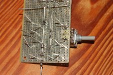
jfets not mounted
actually there are 3 channels
one channel in, split into 2 channels
on board pot is just a channel balance
maybe it could have two functions, and also do tone control work
but I haven't figured that out yet
jfets not mounted
actually there are 3 channels
one channel in, split into 2 channels
on board pot is just a channel balance
maybe it could have two functions, and also do tone control work
but I haven't figured that out yet
Attachments
hi ramallo.
the diagram I find on page 104 of the thread you recommend, is the correct schema with the TL431 as the voltage regulator?
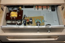
I'd try to build on proto board and having a transformer with 2 secondary to 18v, build it as a pseudo-mono so I can finally trashing this Chinese PCB.
with 18v the value of the resistors (resistor R21 e pot-trimmer R22) on the TL431 will be the same?
thanks for your patience.
the diagram I find on page 104 of the thread you recommend, is the correct schema with the TL431 as the voltage regulator?
I'd try to build on proto board and having a transformer with 2 secondary to 18v, build it as a pseudo-mono so I can finally trashing this Chinese PCB.
with 18v the value of the resistors (resistor R21 e pot-trimmer R22) on the TL431 will be the same?
thanks for your patience.
hi ramallo.
the diagram I find on page 104 of the thread you recommend, is the correct schema with the TL431 as the voltage regulator?
I'd try to build on proto board and having a transformer with 2 secondary to 18v, build it as a pseudo-mono so I can finally trashing this Chinese PCB.
with 18v the value of the resistors (resistor R21 e pot-trimmer R22) on the TL431 will be the same?
thanks for your patience.
Yes, is correct 1k resistor and 10k pot.
The reason of this board is for do fine tuning the voltage value, the distortion values changes a lot with a small voltage changes.
I don't understand well the use of the two secondaries with this board, can you post a schematic or a photo?.
Cheers
Suso
hi ramallo, thanks for the prompt answer.
sorry, i'm just a hobbyist, i have not studied electronics so my technical terms are incorrect.
The first idea was to use a transformer with a double output 0-18v in such a way as to have two separate PCBs, one for each channel.
but 2 Pcb need double the money to populate them with components.
and this is not the moment.
I think instead I will use a transformer with a secondary 32v and follow the pattern as well as it is drawn.
...... I will use a transformer with a secondary 32v ....
32V ac would result in about +45Vdc 😕
well, will remain the other transformer of which I can, later, use the other secondary to power a small headphone amplifier.
I really like the idea of using the TL431 instead of a string of zeners!
I like the adjustability of it.
I like the adjustability of it.
hi ramallo, thanks for the prompt answer.
sorry, i'm just a hobbyist, i have not studied electronics so my technical terms are incorrect.
The first idea was to use a transformer with a double output 0-18v in such a way as to have two separate PCBs, one for each channel.
but 2 Pcb need double the money to populate them with components.
and this is not the moment.
I think instead I will use a transformer with a secondary 32v and follow the pattern as well as it is drawn.
45Vdc is to high, 37Vdc is the max value that a 431 can afford. I suggest you that use just one secondary or connect in parallel both secondaries, or like you wrote in your last message, you can use the unused secondary for other uses such as a headphone amp.
Probably if you had electrolitic capacitors under 50V, you burned all of them (as well the 431)
one more question: the IRF610 can be a good substitute of the IRF614?
thanx
For this use will work
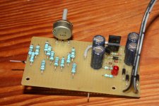
the BoZ gave the first stirrings.
supplied with a switching that comes out to 14.8 v, waiting to fix the power supply recommended.
hums like a hornet but .............. also there is music.
so at first glance it seems to get more down the B1 Buffer, but from the profane i am and after building a power supply as planned, I think the power supply it is very important above all not to do humming.
thanks guys.
- Home
- Amplifiers
- Pass Labs
- Jfet BOZ