Vix said:Back on topic
Jfet BOZ deceived me!
When I built it, I was testing it with amps that do have some voltage gain. With F2 lite, Jfet BOZ was working fine, very clean and musical as well.
What happened? I modified F2 into "Ota-one transistor amplifier". For those that didn't read that thread, that's simply a follower-no voltage gain. So I had to push Jfet Boz more...and then it distorted...
I cut one of 27 ohm source resistors. Became a bit cleaner, but not much...Ok, at low volumes it still sounds wonderful, one of the best combinations ever heard (jfet+ota). This made me want more...but Jboz distorts!
So it seems that it is not capable of swinging enough voltage, or maybe I need to experiment more with resistor values. Or, add two batteries more, and make it 36v supply...
Regards,
Vix
don't ask me.........that's normal- you are limited with bias voltage....... be gratefull and don't expect that one jewel can crown entire city.
regarding gain and swing-today I squeezed 70Vp-p clean sine(at 500Hz) output from Pumpkin ,through 600-600 xformer .....once I laughed ,thinkin how Papa will probably laugh ,knowing possible troubles in reinventing that type of circ........
ZM ........now in Black Adder's dummy period
Nelson Pass said:The circuit has a sweet spot, but outside of that, it won't work
as well.
I forgot, diamonds are small, thus they have a narrow sweet spot 🙂
Zen Mod said:
don't ask me.........that's normal- you are limited with bias voltage....... be gratefull and don't expect that one jewel can crown entire city.
Looks like Nelson has prepared a crown...
We are waiting for the (jfet) king of the preamps....
😎

p.s. Choky, 70 v....scary....

mpmarino said:see post 446.
... now back off topic....🙂
Here's something to stretch your patience while waiting for the Jewel...
Attachments

Please accept that I have limited knowledge and experience on the technical aspects of circuit design.
I can't see how this circuit would work with Vdd being outside the range 30 to 40 volts. 35 volts seems a good choice to me because much below that the transistor will not be in its linear region and a few volts above that it will fail.
The values in Nelson's original circuit seem to be about right to me with the only change could be on the resistor setting Id. It could be reduced from 2k2 to 1k8 and it will still be in its linear region, actually more linear.
I also thought I read Nelson say it needed a load of at least 10k, so using it to drive headphones is not possible.
I only mention this now before I actually "test" anything is because it sounded like this thread was about to die.
So, my guess "sweet spot" is:
30 to 40 volts
1k3 to 2k4
Much outside that limited range => distortion
regards
Blues said:
Here's something to stretch your patience while waiting for the Jewel...
-too masculine.
actually that 'bike' is my fav posted so far. Yes, something to ponder as I wait to find out what what is building block #2......
Blues said:Here's something to stretch your patience while waiting for the Jewel...
Hmmm... I'm sure it could stretch something.
😎
Blues,
You have a dirty mind. Nelson clearly meant that you could extend the front forks on the machine in question, thus gaining more sensitive handling.
Nothing more.
Grey
(But, in fact, Nelson has said a risque thing or two over the years...)
You have a dirty mind. Nelson clearly meant that you could extend the front forks on the machine in question, thus gaining more sensitive handling.
Nothing more.
Grey
(But, in fact, Nelson has said a risque thing or two over the years...)
Aye, and to some people those three words are tantamount to sin and debauchery.
Sadly, those same three words find me at work.
Grey
Sadly, those same three words find me at work.
Grey
Lineup JFET Boz. Low 10kHz THD % distortion version 1.0a
🙂 Hello.
I have already given a short summary of JFET Boz.
And my major testing, as I recall it, used 1.414 Vrms output into 10 kOhm
Quote:
When optimise the drain resistor, (4k7) I could get this down to close 1% THD.
But not any lower.
It should be clearly noted here:
Nelson has never claimed JFET Boz to be a low distortion and HIFI preamplifier.
But instead JFET Boz is an easy very nice project for DIY builders,
that may sound ever so good as any other preamp!
http://www.diyaudio.com/forums/showthread.php?postid=1235352#post1235352
This is not too diferent from Nelson own distortion figures:
http://www.diyaudio.com/forums/attachment.php?s=&postid=1227462&stamp=1181178764
###
My own suggested JFET Boz Variation 1.0a with improved THD: like ~0.020%
was posted much earlier here in JFET Boz topic.
The output voltage during this test was 2 times higher, 2 x 1.414 Vrms = +/- 4.0 Vpeak.
This circuit was optimized for 10 kHz sinus frequency, at this 4.0 Vpk level into 10 kOhm LOAD.
Sort of 'worst case' approach.
Quote:
Comment to my attached SCHEMATIC
Lineup 2SK170GR Jfet BOZ - beta version 1.0a
-
Supply Voltage is 30VDC, well regulated**.
The DC operation voltage at Output node is: ~10.5 VDC.
** I recommend the use of one cheap & good TL431 adjustable zenerdiode ( 2.5V - 36V max)
plus a simple follower NPN Transisitor.
One that can deliver 10mA = total supply current
http://www.diyaudio.com/forums/showthread.php?postid=1228636#post1228636
lineup
Babowana said:
Hmm . . . I'd like try JFET BOZ with J310 instead of 2SK...
J310 has lower transconductance than 2SK...
and will probably give higher distortion . . .
But, is this a considerable problem?
twitchie said:Reporting in:
I tried and tried, but I couldn't get satisfying sound out of this
- I built 2 layouts and protoboarded it,
but I think it needs to be adjusted for each specific setting
according to the rest of the system.
I did find that the zhaolu 2.5 dac puts out a much larger output than my dvd player
-/snip/-
I haven't given up yet though, just taking a break
- I'm planning on building a version with cermets in place of some of the resistors
so I can tweak on the fly
🙂 Hello.
I have already given a short summary of JFET Boz.
And my major testing, as I recall it, used 1.414 Vrms output into 10 kOhm
Quote:
When optimise the drain resistor, (4k7) I could get this down to close 1% THD.
But not any lower.
It should be clearly noted here:
Nelson has never claimed JFET Boz to be a low distortion and HIFI preamplifier.
But instead JFET Boz is an easy very nice project for DIY builders,
that may sound ever so good as any other preamp!
http://www.diyaudio.com/forums/showthread.php?postid=1235352#post1235352
This is not too diferent from Nelson own distortion figures:
http://www.diyaudio.com/forums/attachment.php?s=&postid=1227462&stamp=1181178764
###
My own suggested JFET Boz Variation 1.0a with improved THD: like ~0.020%
was posted much earlier here in JFET Boz topic.
The output voltage during this test was 2 times higher, 2 x 1.414 Vrms = +/- 4.0 Vpeak.
This circuit was optimized for 10 kHz sinus frequency, at this 4.0 Vpk level into 10 kOhm LOAD.
Sort of 'worst case' approach.
Quote:
Comment to my attached SCHEMATIC
Lineup 2SK170GR Jfet BOZ - beta version 1.0a
-
Supply Voltage is 30VDC, well regulated**.
The DC operation voltage at Output node is: ~10.5 VDC.
** I recommend the use of one cheap & good TL431 adjustable zenerdiode ( 2.5V - 36V max)
plus a simple follower NPN Transisitor.
One that can deliver 10mA = total supply current
http://www.diyaudio.com/forums/showthread.php?postid=1228636#post1228636
lineup
Re: Lineup JFET Boz. Low 10kHz THD % distortion version 1.0a
It doesn't take much. A little feedback, and I get .0006% @ 1.4V,
10Kohm with a similar toplogy and 6 dB gain.
.😎
lineup said:My own suggested JFET Boz Variation 1.0a with improved THD: like ~0.020%
was posted much earlier here in JFET Boz topic.
[/i]
It doesn't take much. A little feedback, and I get .0006% @ 1.4V,
10Kohm with a similar toplogy and 6 dB gain.
.😎
FieldEffects in MetallOxides
.
I will study jfets & ultimate use of them a bit further
Nelson,
They Are Nice 😎
And I WILL Be Back
with some new ideas & circuits
using this Theme of JFET.
🙂 Now you are all warned!
/halojoy
.
I will study jfets & ultimate use of them a bit further
Nelson,
They Are Nice 😎
And I WILL Be Back
with some new ideas & circuits
using this Theme of JFET.
🙂 Now you are all warned!
/halojoy
put one these together as my 12db amp combined with low output monica2 dac not cutting it driving the F4...
sounds good. just etched own board as don't have any perf board and needed to put together a power supply anyway. using 25v rectified->1000uf cap -> lm317 to give 18.5 volt out -> 1000uf cap -> 3 10ohm parallel -> 1000uf cap. Have a small ground loop buzz, should i decouple audio ground, or the main circuits ground from power ground with a 3 ohm resistor? Like R0...
Also, should i put 2- 9.1v zeners together for input protection?
Using 2.2k Rd, 22ohm Rs... get 9 volts across drain to source, then 9ma across the Rs
Attachments
Did someone mention Tone Controls ? 😀
 What you require is a REAL bass tone control .... if I may be so bold as to suggest, I have just the thing. You need a very low turnover frequency, with a steep slope.
You have undoubtedly noticed that conventional tone controls - most especially the bass - in a word, suck. The reason is, they use passive R & C networks. Resistors aren't reactive, so that leaves only capacitors to provide the rolloff. This results in a 6 dB/ octave slope. I don't know of cases where it is steeper - it would require even more signal loss, and noise, to create an additional stage. NOT practical.
To make matters worse, the turnover frquencies are also typically high. 250 Hz, 400 Hz, 500Hz ... and even higher.
The sound of these ill-conceived circuits is fat and muddy. I have often thought it would be more honest if they labelled it "MUD" instead of "BASS."
The solution is to create a tone control network with a steep slope and low turnover frequency. I have found that I preferred 75, 90 and 100 Hz for the bass - a choice of 3 different turnovers. I might reduce it to a choice of 2, I don't know. In my experience, some older recordings (The Beatles being a perfect example) sounded best with 100 Hz turnover, and modern recordings, lower.
Originally, I used old transformers for the inductors, I didn't have anything else. I found a couple of about 7 Henries. I bought some tiny audio transformers, using them as inductors, I think they came from Mouser - it is easy enough to check. They are as follows :
XICON TL024 = 6 Hy
XICON TM019 = 13 Hy
XICON TM025 - 20 Hy
I have not tried them yet. Strangely, I discovered I had not
bought the 6Hy units, I have some 13 Hy units instead - it's been a while since I fooled with this.
There are some caveats with this thing :
One, that an inductor can attract some noise - which is really nothing in my experience with even the great big transformers - that was a pleasant surprise. Still, it is possible. I will certainly shield mine.
Two, that my circuit provides NO cut - only bass boost - and yet, to me, it worked fine, I didn't need bass cut - ever. To provide cut .... it may be possible to use the differential ouput of the BoSoZ, if one was so inclined - or - forgive me for this : An op-amp. Very simple matter to wire a pot into the + and - inputs with a differential configuration, all the boost and cut you want, then a summing amplifier.
Three, the slope is not quite as sharp as I would like. There IS some midrange that is affected. The effect is not terrible, but it's there. I have shown L 2 as an additional pole, acting together with the volume control resistance to provide an 18 dB/octave slope. I have not yet fiddled with this - but I expect it to provide
good performance. No value is given, but it would of course be a few Henries. I believe it's impedance, by the book, would need to be much higher than the first stage impedance output - however, one can always fudge.
Four, I simply tacked on a standard type treble boost / cut - and nothing special about that, and variations are possible. It is there to provide treble boost quick and easy, that's all. But that network, as shown, minus L 2 - just leave that out, use a wire there instead - worked okay for me.
Five, You could, of course, build an active filter circuit. Some years ago, I made a 3 or 4 pole - can't remember now - bass tone control using a standard circuit out of Lancaster's book. The treble was also the same number of poles. Then an output differential stage, and a summing amplifier. I prefer this circuit for the sake of simplicity. But the op-amp version did the job ! I will scan it in and post it if asked. I will have to clear a few mental cobwebs first, but it's straight-forward. But I think you want a ready-to-use circuit, not theory.
Six, there is of course, signal loss with this. Or course, since we normally want to add back some of that bass and treble (I often turned the controls to maximum), it isn't terrible. But it is possible the gain of the BoZ might have to be increased.
Seven, I forget the specs of those little transformers, but I think they ought to be able to handle what the BoZ gives them without burnout.
In comparison with the commercial hi fi amps I have around here, this simple circuit made a mockery of them in the bass. The words that came to my mind were "thunder"and "rumble" and it sounded like an extra octave or two had been added. However, it does NOT sound unnatural - it sounds real. I had an equalizer with which I tried to restore the bass - I never could get it right with any system. With this, I don't need it,
Take the volume control off of the BoZ and feed the circuit from the BoZ ouput capacitor, and put the 5 K volume control where it's shown in this circuit.
My reasoning of the circuit is simple enough - but I skip it for now, my post is long enough already. You can see how it works - a low pass filter, and voltage divider, very simple, and the treble, self-explanatory.

I've done that, and I liked the results.I'd like to build a boz and add a tone control to it ...
Yes.I'd like something that boosts upper and lower, leaving midrange frequencies untouched. Is it possible to do?
What you require is a REAL bass tone control .... if I may be so bold as to suggest, I have just the thing. You need a very low turnover frequency, with a steep slope. You have undoubtedly noticed that conventional tone controls - most especially the bass - in a word, suck. The reason is, they use passive R & C networks. Resistors aren't reactive, so that leaves only capacitors to provide the rolloff. This results in a 6 dB/ octave slope. I don't know of cases where it is steeper - it would require even more signal loss, and noise, to create an additional stage. NOT practical.
To make matters worse, the turnover frquencies are also typically high. 250 Hz, 400 Hz, 500Hz ... and even higher.
The sound of these ill-conceived circuits is fat and muddy. I have often thought it would be more honest if they labelled it "MUD" instead of "BASS."
The solution is to create a tone control network with a steep slope and low turnover frequency. I have found that I preferred 75, 90 and 100 Hz for the bass - a choice of 3 different turnovers. I might reduce it to a choice of 2, I don't know. In my experience, some older recordings (The Beatles being a perfect example) sounded best with 100 Hz turnover, and modern recordings, lower.
Originally, I used old transformers for the inductors, I didn't have anything else. I found a couple of about 7 Henries. I bought some tiny audio transformers, using them as inductors, I think they came from Mouser - it is easy enough to check. They are as follows :
XICON TL024 = 6 Hy
XICON TM019 = 13 Hy
XICON TM025 - 20 Hy
I have not tried them yet. Strangely, I discovered I had not
bought the 6Hy units, I have some 13 Hy units instead - it's been a while since I fooled with this.
There are some caveats with this thing :
One, that an inductor can attract some noise - which is really nothing in my experience with even the great big transformers - that was a pleasant surprise. Still, it is possible. I will certainly shield mine.
Two, that my circuit provides NO cut - only bass boost - and yet, to me, it worked fine, I didn't need bass cut - ever. To provide cut .... it may be possible to use the differential ouput of the BoSoZ, if one was so inclined - or - forgive me for this : An op-amp. Very simple matter to wire a pot into the + and - inputs with a differential configuration, all the boost and cut you want, then a summing amplifier.
Three, the slope is not quite as sharp as I would like. There IS some midrange that is affected. The effect is not terrible, but it's there. I have shown L 2 as an additional pole, acting together with the volume control resistance to provide an 18 dB/octave slope. I have not yet fiddled with this - but I expect it to provide
good performance. No value is given, but it would of course be a few Henries. I believe it's impedance, by the book, would need to be much higher than the first stage impedance output - however, one can always fudge.
Four, I simply tacked on a standard type treble boost / cut - and nothing special about that, and variations are possible. It is there to provide treble boost quick and easy, that's all. But that network, as shown, minus L 2 - just leave that out, use a wire there instead - worked okay for me.
Five, You could, of course, build an active filter circuit. Some years ago, I made a 3 or 4 pole - can't remember now - bass tone control using a standard circuit out of Lancaster's book. The treble was also the same number of poles. Then an output differential stage, and a summing amplifier. I prefer this circuit for the sake of simplicity. But the op-amp version did the job ! I will scan it in and post it if asked. I will have to clear a few mental cobwebs first, but it's straight-forward. But I think you want a ready-to-use circuit, not theory.
Six, there is of course, signal loss with this. Or course, since we normally want to add back some of that bass and treble (I often turned the controls to maximum), it isn't terrible. But it is possible the gain of the BoZ might have to be increased.
Seven, I forget the specs of those little transformers, but I think they ought to be able to handle what the BoZ gives them without burnout.
In comparison with the commercial hi fi amps I have around here, this simple circuit made a mockery of them in the bass. The words that came to my mind were "thunder"and "rumble" and it sounded like an extra octave or two had been added. However, it does NOT sound unnatural - it sounds real. I had an equalizer with which I tried to restore the bass - I never could get it right with any system. With this, I don't need it,
Take the volume control off of the BoZ and feed the circuit from the BoZ ouput capacitor, and put the 5 K volume control where it's shown in this circuit.
My reasoning of the circuit is simple enough - but I skip it for now, my post is long enough already. You can see how it works - a low pass filter, and voltage divider, very simple, and the treble, self-explanatory.
I provide this.Are there schematics available?
Attachments
JCM said:Did someone mention Tone Controls ? 😀
 what can i say?! THANK YOU SO MUCH!!!!
A simple and detailed schematic is just what i needed.
I've just read your post in a hurry, i'll come back to it this evening there are a lot of useful informations inside.
i still need some parts in order to get a working BOZ, as soon i'll get them i'll try the tone control immediately.
You're very kind, thanks a lot JCM! 🙂
Marco
THANK YOU SO MUCH
You are welcome. I did do a hurry-up job to create the gif file there, so it's not as neat and clean as it might be.
Of course there are a number of ways to do things, and that circuit was thrown together by me after calculating the XL and XC
of different L and C values. I sought the point where their
reactances were equal at a low frequency. I came by accident, it seems, to almost the exact values prescribed for a 2 pole Butterworth low pass filter. This site, which seems to be malfunctioning right now, gave the values , after the fact :
http://www-users.cs.york.ac.uk/~fisher/lcfilter/
There is a site where a guy created a 3 way EQ for a tube guitar amp, and that's where I found out about those XICON brand inductors :
http://members.aol.com/sbench101/BatteryPoweredAmps/tonestac.html
His network gives actual boost and cut, but not as sharp a rolloff.
To get actual cut from a 3 pole network seems to be trickier - and a reason the idea of using a differential op-amp circuit tempts
me - how simple it would be, and effective.
A circuit like this invites experimentation. I built the BOZ and the tone controls on a solderless breadboard, so I could tinker with it - highly recommended. I built a simple Zen-type amp and a BoZ, and it REALLY needed some bass & treble boost ! I sought the fastest, most effective way to get it - the result is that circuit. I expected it to be too much for the little amp (like 1 or 2 watts at most), but if it can be said that circuits have personalities, the little amp loved it, and the speakers also (and my headphones) , and I really did wonder how THAT much deep bass came out of it. I believe the Class-A bias of the amp is what allowed it to so easily perform well. I expected to hear intermodulation distortion - I swear I heard none.
I also consider using a small value inductor for the treble to get a 12 dB/octave rolloff for that also - in summary, the circuit is a bit ~ rough as it is - but one can fiddle with it all day long, get the best performance. The calculations of Xc and Xl will tell you what's happening, a simple voltage divider equation where Fc is an attenuation of 0.5, because that's where Xc and Xl meet, and you can draw a graph of it.
You'll have to hear it to really know. I would be happy to know it worked well for you! I must also admit, it, like everything, certainly has flaws.
I will also say, compared to countless passive tone controls - it beats the devil out of them.
I would not be surprised to know there are better circuit arrangements - this one is truly "quick and dirty". I include a variation - but looking at it, I see how the 13K resistor, at
minimum bass, would act as a shunt to reduce the entire volume -(of course, if that was another inductor, it would attenuate bass frequencies - at a shallower rate). Putting a resistor in series with the bass pot to ground would reduce the effect. The reason for this different arrangement is that it ought to give a smoother transistion than the original - with the original, a reverse log or log pot might be necessary. You can see I tacked on a different treble network to this one. Once I get back to it, I will probably use an LC string the reverse of the bass string to achieve 12 dB treble rolloff - there's a lot of room for experimentation !
Believe me, I am happy to talk of tone controls all day long! I have to limit myself! I hope to see you get good bass (that's the hardest to achieve - treble seems to be pretty easy). And if need be, we can get an 18 dB/octave boost-cut op-amp circuit going, and I think that will do the job!
Attachments
I had forgotten to mention another type of tone control circuit which has been in vogue for a while. Also, it's true that this is a different topic than the J-FET BoZ - apologies are offered for that.
Rod Eliot offers a preamp design, and the tone controls are of interest. Looking at the graph, it seems to be another 6dB/octave circuit, and he says it is a Baxandall type network (which, it looks to be on first sight just that) with some modest improvement. Credit is due to him for recognizing the value of tone controls and also the uselessness of the insane turnover frequencies often used. However, that circuit still leaves a lot to be desired, and the technique I used is superior. I have seen this same design years ago; it is better than passive RC, but not worth building imo. I would even go so far as to claim that his preamp is NOT hi fi. Once you hear actual bass, you can't listen to these circuits with enjoyment - it is a parody of hi-fi. Here is the circuit :
http://sound.westhost.com/project97.htm
The excuses used to avoid inductors, that they're are bulky and noisy is not valid, not anymore.
Can I use a 2SK30GR or even a 2N3819 in the J-FET-BOZ circuit? And how should I alter the resistor/voltage values?
(I - ahem - happen to have 2sk30ies and 2N3819s, but no 2sk170ies...)
Any ideas?
(I - ahem - happen to have 2sk30ies and 2N3819s, but no 2sk170ies...)
Any ideas?
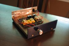
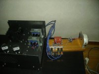
Here´s a picture of my line amp, inspired by the schematic in post #2. I use BF245B Jfets with different resistor values, everything is hardwired to volume pot.
The PSU is a simple Mosfet based capacitance multiplier and a 24V 30VA transformer (vastly overrated, the whole this draws abut 10mA...)
It took me a couple of hours to build this thing and it will be replaced with a 12B4A WOT linestage very soon.
I bought 50x J310 Jfets on Ebay a couple of days ago though so this will probably not be my first and only Jfet line amp.
Edit: Obviously, the linestage is the thing to the right, assembled on the piece of oak. The thing to the left is my 6AV5GA SE amp.
Attachments
- Home
- Amplifiers
- Pass Labs
- Jfet BOZ