2SK170GR Idss measurements
I have just received a batch of 2SJ170GR from Futurlec (good price and fast postage) and measured the Idss to match two of them for the JFET BOZ.
The first measured 3.29mA, which seems within the GR range, but then the remainder measured from 13.84mA to 19.75mA. I have three pairs matched to .5%, which, to my limited experience with FETs, seems very good.
However, I am a little perplexed by the measurements. I thought that GFS had a generally lower Idss than the BL. I have just matched 2 pairs of the 2SK170BL with Idss of 7.45mA, for use as differential input pairs in a pair of discrete op-amps (Pass simple discrete op amp). The remainder of the batch ranged from 5 to 10mA.
I have checked several times and the GRs Idss still measure almost double the BL. Is this something to be concerned about, or can I just be happy that I have 3 closely matched pairs of 2SK170GR from a batch of 10?
I can use one pair of the matched GRs (13.84mA) in the JFET BOZ and another pair (14.5mA) in the CCS for the two differential pairs of BL.
Thanks
Joe
jnewbold said:the remainder measured from 13.84mA to 19.75mA.
I'd rather have K170V labelled as K170GR than the other way round.

jacco vermeulen said:I'd rather have K170V labelled as K170GR than the other way round.
Yes, thanks, I guess you are right. I'll just continue on with my projects then.
Best wishes for the new year.
Joe
tschrama said:
I have just received my HP339A last week, and this gave me a perfect oppertunity to play with it....I measured the original schematic as postec by Nelson on post#2 with a few JFETS.. 1Vrms out, 1KHz, here goes:
Idss=14mA, optimum Vsupply = 24.5volt, THD=0.17% pure H3, gain =28dB
JFETs with simmilar Idss measured the same THD, gain and optimum Vsupply...
Hi,
I have made up a JFET BOZ using 2SK170s almost perfectly matched with Idss of 13.83mA and 13.84mA. Based on the data for 14mA from tschrama in post #577 (part quoted above) I used a 24.5V supply and the resistor values originally posted by Mr Pass. However, distortion was quite noticeable.
Measured 2.5V at Rd, 101mV across Rs and about 2.5V from drain to source.
After re-reading much of the thread tried a few different resistors in parallel with Rd until at 1.35K, I have 7.55V from drain to source and 109mV across the source resistor, almost 11mA!
The thing is really singing now with no trace of distortion and it sounds as good as my original BOZ, only slightly more airy and with a deeper and wider soundstage.
I have tried lowering the supply voltage and altering the value of the drain resistor, but always come back to the present set up with all resistors as original except 1.35K at the drain.
Is this difference due to the higher Idss of the JFETs I am using?
Another question. How crucial is the value of the (470R) resistor after the output cap and what are the practical limits to its value?
Thanks,
Joe
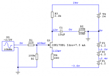
JFET BOZ idea in this thread is troubled with too much gain that 2SK170 gives. To make it acceptable we attenuated the input signal and overloaded the output, whic are not my favorite strategies, so I tried it a bit differently: small negative power supply to Source pin so we can have small gain (6-12 dB, 2 x - 4 x) and high bias (5.5 mA with 7.5 mA Idss JFET) at the same time.
Negative PS is made from 3 x 1.2V rechargeable battery cells or cell-phone battery (most of them are 3.6 V). With 5.5 mA draw either will last for a long time.
I used existing +24V PS but higher PS voltage (up to +35 V) won't change anything important.
Playing with R3, R4 and -PS voltage may give other interesting results. This version works nice for me.
This JFET BOZ can put out clean 5V RMS and it drives F5 very nicely. For some other uses as a preamp it will love B1 on its' output.
Attachments
Sorry, if repeating : what are input impedance (1 meg?) and output impedance of JFET BOZ?
I am thinking about using it as gain stage (with 14 NiMH AAA cells) for a modified NOS DAC TDA1543 (ecdesign) before my Lightspeed pre.
: what are input impedance (1 meg?) and output impedance of JFET BOZ?I am thinking about using it as gain stage (with 14 NiMH AAA cells) for a modified NOS DAC TDA1543 (ecdesign) before my Lightspeed pre.
Tolu said:Sorry, if repeating
Input impedance is dominantly determined by the value of the resistor that connects JFET's gate and ground, but with this type of circuit (common source amplifier) the JFET's input capacitance is not negligible (it makes an LP filter with input resistance). I would keep that resistor at 100k max.
Output impedance roughly equals the Drain resistor's value.
juma said:
Input impedance is dominantly determined by the value of the resistor that connects JFET's gate and ground, but with this type of circuit (common source amplifier) the JFET's input capacitance is not negligible (it makes an LP filter with input resistance). I would keep that resistor at 100k max.
Output impedance roughly equals the Drain resistor's value.
In the original schematic input impedance would than be 1,001 meg Ohm.
The drain resistor you meant, is it the 475 Ohm one?
Usually the relatively low output impedance of whatever is driving the
Gate dominates the high frequency rolloff, so feel free to try whatever
input resistor you want.
😎
Gate dominates the high frequency rolloff, so feel free to try whatever
input resistor you want.
😎
Nelson Pass said:Usually the relatively low output impedance of whatever is driving the
Gate dominates the high frequency rolloff, so feel free to try whatever
input resistor you want.
😎
Relatively low output impedance of, let's say, grounded cathode amplifier that can often be found in many DACs' output stages, or maybe relatively low output impedance of passive I/V convertors used as an output stage of many DIY NOS DACs ?
But, actually, you are right, he should be free to try everything, that's the best learning method - though expensive sometimes 😀
Nelson Pass said:Usually the relatively low output impedance of whatever is driving the
Gate dominates the high frequency rolloff, so feel free to try whatever
input resistor you want.
😎
Was this correct what I assumed? 475 for output and 1 meg for input?
I just ask because of the need of relatively high input impedance (>25k) and relatively low output impedance (< 700 ohm).
Attachments
Lieber Tolu,
Drain resistor is 2.2k and 475 is a short circuit protection resistor. Added together they approximately represent the output impedance of this circuit. 10 uF output capacitor contributes a bit, but it is negligible in audio band for loads higher than 10k.
If you want lower output impedance use B1 on JFET BOZ's output.
Gruesse!
2.2 plus 0.475 gives 2.7 kOhm output impedance? Way too much for my Lightspeed! Than I have to put the Lightspeed at that position where in the original schematic the 25k pot is and drive the Lightspeed with 50kOhm input impedance.
I put my Lightspeed in front of the JFET BOZ, and both powered by a pair of 9V batteries in series.
Worked very nice. Only other thing was I put a 1.0uf cap instead of a 10uf PP cap on the JFET BOZ by accident. Never realized it until recently...
Worked very nice. Only other thing was I put a 1.0uf cap instead of a 10uf PP cap on the JFET BOZ by accident. Never realized it until recently...
Tolu said:2.2 plus 0.475 gives 2.7 kOhm output impedance? Way too much for my Lightspeed! Than I have to put the Lightspeed at that position where in the original schematic the 25k pot is and drive the Lightspeed with 50kOhm input impedance.
That particular circuit has two 2.2K resistors at the output, one to
ground and the other to rail, so that they parallel (for AC) to form
1.1K. Add that to your 475 and you get approximately 1.6K.
😎
Nelson Pass said:
That particular circuit has two 2.2K resistors at the output, one to
ground and the other to rail, so that they parallel (for AC) to form
1.1K. Add that to your 475 and you get approximately 1.6K.
😎
Do you know a legerdemain how to drop output impedance <1k without sonical degradation?
OFF TOPIC ON
After discussing the word "legerdemain" with a colleague from Ohio, she regretted not to know this word. I got this from several english-german dictionaries and it means the same than "magic trick".
OFF TOPIC OFF
After discussing the word "legerdemain" with a colleague from Ohio, she regretted not to know this word. I got this from several english-german dictionaries and it means the same than "magic trick".
OFF TOPIC OFF
what happens when I reduce the value of the 2.2k resistors to e.g. 1.5k and the 475 to 220 ohm? Sorry, but I have no scope or simulator!
Tolu said:
what happens when I reduce the value of the 2.2k resistors to e.g. 1.5k and the 475 to 220 ohm? Sorry, but I have no scope or simulator!
I believe that the voltage gain will be reduced.
R of 475 ohms is there to prevent potential oscillation . . . I think.
220V might be okay . . . tho . . .
- Home
- Amplifiers
- Pass Labs
- Jfet BOZ