Remember to check your cascade of output offsets.
If it gets too high you may want to consider the Feucht added source resistor.
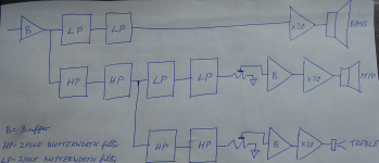
The Bass needs a 4pole Low Pass LR
The mid needs a 4 pole High Pass LR and a 4pole Low Pass LR. The Low Pass LR feeds the Mid amp. The output of the High Pass LR feeds the treble stage.
The treble needs a 4 pole High Pass LR.
This gives the basic LR4 3way. All the 2pole stages are Butterworth.
You may want to consider adding a High Pass for the Bass to protect against over excursion.
And consider a Low Pass for the treble to cut a bit more of the RF.
And attenuation+Buffer for the two most sensitive drivers.
And Baffle step for the Mid.
And some other EQs for any or all three drivers
And .....
If it gets too high you may want to consider the Feucht added source resistor.
The Bass needs a 4pole Low Pass LR
The mid needs a 4 pole High Pass LR and a 4pole Low Pass LR. The Low Pass LR feeds the Mid amp. The output of the High Pass LR feeds the treble stage.
The treble needs a 4 pole High Pass LR.
This gives the basic LR4 3way. All the 2pole stages are Butterworth.
You may want to consider adding a High Pass for the Bass to protect against over excursion.
And consider a Low Pass for the treble to cut a bit more of the RF.
And attenuation+Buffer for the two most sensitive drivers.
And Baffle step for the Mid.
And some other EQs for any or all three drivers
And .....
Here is the HP sch and the 3way for an LR4
I have not implemented any EQ yet.
Will listen for a long while before I think about adding anything.
Note that with the HP, the input cap to each filter blocks the previous output offset.
Only in the LP & B do the offsets add up.
Thus the mid has 4 cascaded stages that should be checked for excessive output offset. The bass has 3 cascaded stages.
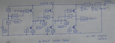
I took the power from the raw PSU +ve and 0V of the power amp. That's why I incorporated RCRC and used fairly high values of R (330||330) to drop the voltage.
I have not implemented any EQ yet.
Will listen for a long while before I think about adding anything.
Note that with the HP, the input cap to each filter blocks the previous output offset.
Only in the LP & B do the offsets add up.
Thus the mid has 4 cascaded stages that should be checked for excessive output offset. The bass has 3 cascaded stages.
I took the power from the raw PSU +ve and 0V of the power amp. That's why I incorporated RCRC and used fairly high values of R (330||330) to drop the voltage.
Attachments
Last edited:
Thank you Andrew, (like we said in Spanish) "an image suits more than one thousand words". Could you post the LP filter? Attached your schematic with some doubts that I have? what are the bias voltage value? could I use other FETs? I guess isn't necessary to be matched, right?
Last edited:
The bias voltage is set with the 10k & 9k1. Smoothed with the 220uF.
I set it very slightly below 50%, to get a little further away from the 2nd harmonic that sets in with single ended followers at the extremes of input voltage.
You should be able to get a fairly clean 5Vac with 19V on the supply. This is well above (+6dB) the 2.2Vac to 2.4Vac that comes from highish output CDP. I don't know if any other Source is higher.
Sorry my ignorance, 2R are connected to 10k 9k1 bias? Could you post schematic for low pass filter?
C, R and 2R (different from 2r2) are the Frequency and Q setting components.
You already have the Low Pass in post 121 !
You already have the Low Pass in post 121 !
Last edited:
I usually measure from the Zero Volts line.
Sometimes I measure across a component.
In both cases it should be clear which is being used.
Your measurements should be just as unambiguous.
Sometimes I measure across a component.
In both cases it should be clear which is being used.
Your measurements should be just as unambiguous.
I have different amps for each way, how to balance to have the same gain in each way? Are the trimmers between the filters & buffers? If yes wich value and how measure to have the same gain in each way?
Last edited:
- Status
- Not open for further replies.
- Home
- Source & Line
- Analog Line Level
- JFET Active Crossover