Not totally both, but somewhere in between.rcw said:... indicating that it is not c.d.: can we then make a horn that does both?
At the moment I don't know, and am looking at methods of finding out.
It seems Ed that there is a semantic issue to do with the definition of c.d. here.
And the speaker system in question probably does not have constant power responce above a certain frequency, and if you require this for your definition then by definition it is not.
Rcw.
Ed LaFontaine said:...or that "constant directivity" for the OS waveguide is a misnomer?...due to the "hole in the middle"?
In PRO audio (PA applications) people are not as picky about the last dB as in homeFi.
They feel pretty comfortable as long as they mange to keep within 10dB off target
😉
No need to crank expectations too high..
soongsc said:
Not totally both, but somewhere in between.
Yes your contour looks very good in the directivity sonogram I calculated with the plain wave front injected – it might even look better if you could show *your* directivity sonogram with the concave driver you use?
rcw said:can we then make a horn that does both?
Rcw.
Working on that – lets see what else new coming up besides "my whale" and soongsc's contour – we just started to more precisely set the new goal "min phase behaviour" – John Kreskovky's idea isn't really wide spread at the moment.
Might be there are some other directivity sonograms about ancient CD contours around ?
Michael
Michael,
I've been tweaking the model, so it's changed somewhat. The data I have already posted is here.
http://www.diyaudio.com/forums/showthread.php?postid=1887491#post1887491
I've been tweaking the model, so it's changed somewhat. The data I have already posted is here.
http://www.diyaudio.com/forums/showthread.php?postid=1887491#post1887491
Hello,
In french, I use "transmission" or "resistive impedance", in acoustic, it means the same thing for me.
It's analogical with electricity and R (ohm), synonim of no dephasing.
rcw said:A more correct term for the field is a scattering field as this includes the diffraction and the reflection from the impedance anomaly at the mouth.
The value of this description is that it makes clear that the minimum reflection is also the minimum diffraction.
What we want ideally is a transition to "pure diffusion", in which all scattering is forward and divergent, (diffraction is scattering off boundaries), and the ideal beam has a Gausian envelope.
rcw.
In french, I use "transmission" or "resistive impedance", in acoustic, it means the same thing for me.
It's analogical with electricity and R (ohm), synonim of no dephasing.
rcw said:From what I have seen the sonogram of the LeCleche type horn produce a Very Gaussian like distribution at nearly all frequencies but it has the characteristic “fat whale”, shape, indicating that it is not c.d.: can we then make a horn that does both?
It's just an opinion, but i think it's a typical technical compromise, like rigidity and lightness.
thend said:
It's just an opinion, but i think it's a typical technical compromise, like rigidity and lightness.
We'll need a looot of patience to find out, I'm afraid.
My most recent simus indicate that there is "generally" an overlay to be observed from what the horn does in "concentrating energy" to a certain room angle (or is supposed to do) and what comes from mere limitation of horn size.
If I run "my whale" on higher resolution we begin to see the same pattern - at a veeery attenuated level of course - as we see from the pure direct radiators.
It starts to look like smooth folds in the whales skin.
Basically what I said to be "the bones" - if appearing more pronounced.
The shape of the folds / bones changes with frequency as is for the direct radiator.
The higher resolution simu for the LeCleach is running - will see if it shows up there as well.
This "overlay of bones" expresses as ripples in the FR plot - unfortunately the ripples shift with off axis angle - so benefits of equalising is limited.
Working on a tool to "compress" co-ordinate points of a horn contour to minimise BEM nodes and speed up simulation *without* compromising accuracy
Michael
From what said in my posting before I'd like to draw your attention to the region between roughly 3kHz to 10kHz
Though measurement and sim are not from the same contour the pattern of ripple shifting with off axis angle that express as "smooth folds in the whales skin" in the directivity sonogram are obvious.

compare above pix to soongsc measurements - third from bottom - taken from
http://www.diyaudio.com/forums/showthread.php?postid=1887771#post1887771
In comparison the LeCleach contour simulated at comparable resolution:

No folds or bones to be seen appering
Michael
Though measurement and sim are not from the same contour the pattern of ripple shifting with off axis angle that express as "smooth folds in the whales skin" in the directivity sonogram are obvious.
compare above pix to soongsc measurements - third from bottom - taken from
http://www.diyaudio.com/forums/showthread.php?postid=1887771#post1887771
An externally hosted image should be here but it was not working when we last tested it.
In comparison the LeCleach contour simulated at comparable resolution:
No folds or bones to be seen appering
Michael
Soongsc, in the light of above your latest contour (fourth from bottom) definitely is a big improvement.
Though the ripples there are more pronounced – they are almost congruent in frequency over off axis angle - which is much more important with respect to advanced EQing.
How did you achieve that?
Michael
Though the ripples there are more pronounced – they are almost congruent in frequency over off axis angle - which is much more important with respect to advanced EQing.
How did you achieve that?
Michael
I really don't think the last configuration I posted is ideal yet. But basically it's a series of sims, looking at the result and tweaking it. Basically it's systematic tweaking till I get some feeling which part of the horn/guide effects what part of the response.
Just the small ripples in the response probably will have you be viewed with the CSD to determine what effect it has during listening.
Just the small ripples in the response probably will have you be viewed with the CSD to determine what effect it has during listening.
Some axidriver plots of the 3kHz. waveguide i described in the small satellite speaker article...
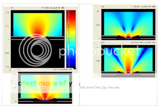
There is now no hole in the middle.
rcw.
There is now no hole in the middle.
rcw.
rcw said:
There is now no hole in the middle.
rcw.
An axial hole is never a problem with a waveguide that shallow. It only begins to be a problem with a much larger device with a much narrower directivity. The hole moves higher with a smaller waveguide or wider waveguide, so the one that you show puts it well out of band.
I wonder how they qualify that as 3KHz waveguide. It does not seem to have very much effect on dispersion control.
That waveguide is a good match for the driver used with it at a 3khz. crossover.
The 3kHz. device does not have two Freznel zones within its aperture until around 17-17kHz. at which point the 25mm. dome has reduced to a beam width of around 45 degrees. The total aperture is not then illuminated sufficiently for phase cancellation to occur.
rcw.
The 3kHz. device does not have two Freznel zones within its aperture until around 17-17kHz. at which point the 25mm. dome has reduced to a beam width of around 45 degrees. The total aperture is not then illuminated sufficiently for phase cancellation to occur.
rcw.
Don't know the specifics, but if the design is what the designer intended, I'm not sure what can be discussed? Each designer has his own priorities.
rcw said:Some axidriver plots of the 3kHz. waveguide i described in the small satellite speaker article...
There is now no hole in the middle.
rcw.
Nice work.
Do you still have the simus and could you please show the directivity sonogram of that shallow waveguide?
Would be interesting to compare with the dicect radiators feom my simus before.
Michael
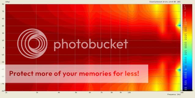
A sonogram of the 3kHz. waveguide directivity..

A friend of mine says it reminds her of something; I can't imagine what she means.
rcw.
A friend of mine says it reminds her of something; I can't imagine what she means.
rcw.
Thanks a lot for sharing!
Seems at 30deg off axis and above 10k you get dips around 10dB -15dB deep.
Below 10k this WG looks pretty good to me.
How tight is correlation with measurements?
MichaelMichael
Seems at 30deg off axis and above 10k you get dips around 10dB -15dB deep.
Below 10k this WG looks pretty good to me.
How tight is correlation with measurements?
MichaelMichael
In measurement those dips are within 6bd. out to around 45 degrees.
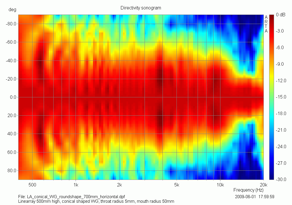
This system was originally planed for a tweeter like this...
This is a 19mm. Tweeter in a waveguide that starts at an included angle of fifty degrees.
Up to 10k it isn't quite so smooth but it is better thereafter.
Rcw.
This system was originally planed for a tweeter like this...
This is a 19mm. Tweeter in a waveguide that starts at an included angle of fifty degrees.
Up to 10k it isn't quite so smooth but it is better thereafter.
Rcw.
rcw, there seems to be a trade off hard to decide which one is better in the end.
First pix is better up to 10k - second pix shifts severe ripples almost out of band but introduces a "new" irregularity at 6kHz
The sound field distribution of your WG seem to be still pretty closely related to the "christmas tree / pagoda" pattern – my guess is that the relatively huge angle of the "scattering junctions" at the WG throat is causing that.
Same as for direct radiators – angle there is full 180deg included.
When working on "my whale" I made the same observation, Earl is emphasising on – any angle at the throat that does not fit the entering wave front causes severe sound field defects - though there are other things to keep in mind too –as seen by the sub-optimal sound field created by the "pure" OS.
As far as I have come now (still waiting for delivery of my fast machine 🙁 ) the LeCleach contour simply is not to beat in its smoothness.
I'm concentrating on bending its overall directivity towards constant directivity by not (as good as it gets) compromising its complete absence of "Swiss cheese defects".
You mentioning Gauss inspired me to use his curve in an overlay to the LeCleach contour and it seems to work pretty well.
You referring to your line array?
http://www.diyaudio.com/forums/showthread.php?postid=1745665#post1745665
http://www.diyaudio.com/forums/showthread.php?postid=1842199#post1842199
Below are simus of a 2m / 80" driver in infinite baffle


Directivity sonogram I did with different SPL-color scalings to show that there are some "Swiss cheese" defects also at on axis FR.
The 4kHz sound fileld I did on a 5m scale to better show the beam keeping narrow over longer distances.
Not too far from what you measured in its overall pattern, I guess...
🙂
Michael
First pix is better up to 10k - second pix shifts severe ripples almost out of band but introduces a "new" irregularity at 6kHz
The sound field distribution of your WG seem to be still pretty closely related to the "christmas tree / pagoda" pattern – my guess is that the relatively huge angle of the "scattering junctions" at the WG throat is causing that.
Same as for direct radiators – angle there is full 180deg included.
An externally hosted image should be here but it was not working when we last tested it.
When working on "my whale" I made the same observation, Earl is emphasising on – any angle at the throat that does not fit the entering wave front causes severe sound field defects - though there are other things to keep in mind too –as seen by the sub-optimal sound field created by the "pure" OS.
As far as I have come now (still waiting for delivery of my fast machine 🙁 ) the LeCleach contour simply is not to beat in its smoothness.
I'm concentrating on bending its overall directivity towards constant directivity by not (as good as it gets) compromising its complete absence of "Swiss cheese defects".
You mentioning Gauss inspired me to use his curve in an overlay to the LeCleach contour and it seems to work pretty well.
tiki said:Hello,
I do not want to bother the other readers, because it was already shown and shortly discussed with Earl. Look through the "neighbour" directory, it is not only a simulation.
Regards, Timo
You referring to your line array?
http://www.diyaudio.com/forums/showthread.php?postid=1745665#post1745665
http://www.diyaudio.com/forums/showthread.php?postid=1842199#post1842199
Below are simus of a 2m / 80" driver in infinite baffle
Directivity sonogram I did with different SPL-color scalings to show that there are some "Swiss cheese" defects also at on axis FR.
The 4kHz sound fileld I did on a 5m scale to better show the beam keeping narrow over longer distances.
Not too far from what you measured in its overall pattern, I guess...
🙂
Michael
Hello,
thanks for the simulations. One should differ between horizontal and vertical directivity/sonograms, but you did, I'm sure.
The lobing effect and its influence on the amplitude response is already described in the well-known Ureda paper "Line Arrays: Theory and Applications". I am convinced that the LA has major advantages over a point source anyhow. Normally I cannot hear the "gaps" while playing music, although they are measurable.
Regards, Timo
- Home
- Loudspeakers
- Multi-Way
- Jean Michel on LeCleac'h horns