Not sure if this should be in Jean-Michel's thread or Lynn's thread. But as Both have a lot of horn/waveguide info here goes...
OK, after taking a close look at the throat mismatch on the PE waveguides and screw on adapters the differences are not as big as I was expecting. Should be a good data point though.
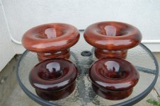
First a photo of the throats of the horns with the unmodified horn on the left.
An externally hosted image should be here but it was not working when we last tested it.
Gary
When it's at it's worst - it's not from a deviation in expansion, but rather contraction - an un-planned diffraction element that covers over the exit.
Beautiful repair job btw.. 🙂
I'd have called it the beginning, not the end but could be a simple misunderstanding. I was idealising, sure, but the point I was making is that the bends you pointed out (WRT diffraction) don't necessarily appear as bends to the wavefront.
Ok, I see how that might be possible. The phase plug ends at the points I highlighted. So, is the wavefront acting like air in a bass reflex box, i.e, it acts as a mass? If yes, then why would it behave differently when it encounters another bend?
In a bass reflex box or even a closed box, the wavelength is much larger than the dimensions of the box, and the trapped air acts like a mass/spring system. For a 2" exit driver, a wavelength corresponding to a frequency of 6810 Hz is where it would get too small for the exit. For a 1" driver, it would be twice this frequency. But below that it would just bend around the edges.
Is this correct, or am I missing something?
In an ideal world the horn would begin at the diaphragm, and wouldn't notice the transition between the region with the slits and the consolidated throat, or the horn proper.The phase plug ends inside the driver and there is an opening with finite length before the exit. The device with no throat would have a 0 degree exit angle, correct?
It would be presumptuous for the compression driver manufacturer to begin a horn profile when it is the end user that wants to specify the horn. They might choose instead to make use of this length inside the driver body by specifying a wavefront shape that can be worked with by a generic horn. The exit angle could be anything they wanted, but it is probably better to keep the throat expanding and so to make the exit angle more than 0.
I've drawn a horn that uses a divider, and provided the pressure on each side of the divider is the same, the horns should function the same as each other. Bends won't have an effect below a certain frequency. It is up to the phase plug designer to make this work to a useful upper limit.
Attachments
I've drawn a horn that uses a divider, and provided the pressure on each side of the divider is the same, the horns should function the same as each other. Bends won't have an effect below a certain frequency. It is up to the phase plug designer to make this work to a useful upper limit.
Ok... so bends are not having an effect below a certain frequency in the driver. Would it be the same when the wavefront reaches the horn? I'm really trying to understand this. Thanks!
I was a bit surprised that that much change in the throat didn't have more influence on the FR. Also interesting was that there were changes in the impedance in the 700Hz to 3Khz range but only very small changes in the FR in that range.
To make things easier to compare, here is an image with 1/6 octave smoothing applied and no offset. Also included in this image is the FR of the D250P on one of the 1K JMLC horns I've turned.
Red is the unmodified 12" PE waveguide + adapter, blue is the modified 12" PE waveguide + adapter and green is the 1K JMLC horn. The same PE D250P-8 driver is used for all 3 measurements.
An externally hosted image should be here but it was not working when we last tested it.
Hmm ... there's a pretty good-sized notch at 3.5 kHz with all three horns; it must be the compression driver. An error in the phase plug design, or a reflection from the rear surface of the compression driver back chamber? It's too low of a frequency for the diaphragm to break up.
The JMLC doesn't look too happy either, with a succession of 2 to 4 dB response dips at 650 Hz, 2 kHz, 3.5 kHz, 5.5 kHz, and 8 kHz. Looks like some kind of termination problem, at least with the PE 250P-8 driver. When I see a cascade of response dips, it reminds me of comb filtering, a sign of a time-domain reflection somewhere. It would be useful to see if one or more discrete reflections can be seen in the impulse response.
Last edited:
Hmm ... there's a pretty good-sized notch at 3.5 kHz with all three horns; it must be the compression driver. An error in the phase plug design, or a reflection from the rear surface of the compression driver back chamber? It's too low of a frequency for the diaphragm to break up.
The JMLC doesn't look too happy either, with a succession of 2 to 4 dB response dips at 650 Hz, 2 kHz, 3.5 kHz, 5.5 kHz, and 8 kHz. Looks like some kind of termination problem, at least with the PE 250P-8 driver. When I see a cascade of response dips, it reminds me of comb filtering, a sign of a time-domain reflection somewhere. It would be useful to see if one or more discrete reflections can be seen in the impulse response.
Agreed. The D250P driver does not look all that good. The response dips are common across the 4 different horns I have available for testing. The impedance curve shown in post #1545 shows many small resonances, especially above 10K.
I guess we can't expect too much for a low cost driver. Got these on sale for $38.00 each.
Also on hand is a pair of Radian 475pb CD's but they measure pretty rough above 6K.
Currently looking for a compression driver that measures much flatter than this for testing the horns I'm turning. Thinking that the B&C DE250 or the Faital Pro HF104 drivers might be good choices based on the manufacturers data, if the FR graphs have anything to do with the real world.
Any input on 1" drivers that measure well is most welcome.
Image of the D250P driver on 4 different horns to show that the succession of 2 to 4 dB response dips are common to the driver.
An externally hosted image should be here but it was not working when we last tested it.
I wouldn't say there is a difference, although perhaps there is more of a concern with path length differences around the phase plug and more of a concern with diffraction later.Ok... so bends are not having an effect below a certain frequency in the driver. Would it be the same when the wavefront reaches the horn? I'm really trying to understand this. Thanks!
It isn't always easy to tell by looking at the contour whether there will be an issue, even straight sided horns have diffraction. As a rule of thumb I'd suggest that if a bend is encompassed within a quarter wavelength it might not be noticed. on the other hand even small ridges across a horn can produce a noticeable effect (fractions of a mm for tweeter).
Also on hand is a pair of Radian 475pb CD's but they measure pretty rough above 6K.
They sound fantastic though.
Any input on 1" drivers that measure well is most welcome.
BMS 4550. But there is a notch at 18 kHz.
There is supposed to be a Be (truextent) version of the 475 directly available from Radian.
This would probably solve most of the problems above 6kHz... (even & 4" truextent Be diaphragm is quite smooth up to 16 or 18kHz, so I imagine a 1.75" one will easily reach 20kHz in the same conditions (pistonic), if the phasing plug is not ill-made.
This would probably solve most of the problems above 6kHz... (even & 4" truextent Be diaphragm is quite smooth up to 16 or 18kHz, so I imagine a 1.75" one will easily reach 20kHz in the same conditions (pistonic), if the phasing plug is not ill-made.
There is supposed to be a Be (truextent) version of the 475 directly available from Radian.
I asked Radian about the Be diaphragm this spring and got a reply 12:th of march:
Sorry but the beryllium diaphragms are not for sale at this time. The beryllium units we received were for testing.
I´ll ask them again.
Agreed. The D250P driver does not look all that good.
.
.
.
Any input on 1" drivers that measure well is most welcome.
Gary, the more interesting thing I took away from your graphs is the lack of change in frequency response after the modifications. And that is probably independent of drivers.
By the way, I tested a bunch of 1" drivers here:
1 inch CD Comparison (SEOS18)
The DE250, Erich's DNA360 and BMS 4550 were the best. I thought the BMS just edged the others in terms of smoothness and distortion. By smoothness, I mean narrowband smoothness, i.e., the absence of small wiggles. The larger trends obviously need to be EQed.
I'm using the Faital HF144 on a SEOS-24. It needs a fair bit of EQ. But it sounds quite good.
Last edited:
Gary, the more interesting thing I took away from your graphs is the lack of change in frequency response after the modifications. And that is probably independent of drivers.
By the way, I tested a bunch of 1" drivers here:
1 inch CD Comparison (SEOS18)
The DE250, Erich's DNA360 and BMS 4550 were the best. I thought the BMS just edged the others in terms of smoothness and distortion. By smoothness, I mean narrowband smoothness, i.e., the absence of small wiggles. The larger trends obviously need to be EQed.
They were probably best because phenolic drivers are more forgiving to horns with a bad shape or too hard material. Try paper horns for upper midrange frequencies. Then the phenolic diaphragms are not needed for it to sound smooth. Except if it is chinese Ti diaphragms. That will sound bad no matter what you do
Last edited:
I´ll ask them again.
They now have Beryllium diaphragms!
We have been working for about a year with the company Materion-True Extend for getting Beryllium material for making diaphragms. At long last we are now producing all the diaphragms for all our compression and coaxial drivers, current product as well as those produced for years.
I am using a curve inspired by LeCleach on my latest speaker.
Here is how you can approximate a LeCleach curve quickly and inexpensively.
This might be a good option for people who are too lazy to build molds.
Here's how you do it:
1) First, make the horn in Hornresp, using the standard methodology of simulating a LeCleach curve. (documented in the help file.)
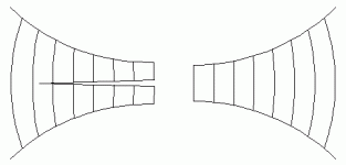
2) I believe you can approximate a LeCleach curve by combining a conical horn with a monster roundover. In the pic above, I am illustrating how to do this. You basically cut the horn right down the middle. The left hand side is the conical side; the right hand side is created with a roundover.
When I say 'monster roundover' I mean it; in the horn above the roundover is a full eighteen centimeters long.
Making the conical section is fairly simple; it can be made with wood and the sides can be calculated in a few minutes. Bill Waslo has a spreadsheet that can calculate conical horns too.
The roundover is a little bit trickier. I am personally using sonotube. For my horn I should be using a 14" sonotube, but 13" was the biggest size I could find at my Home Depot.
Mating the two sides is up to you. I am going to use fiberglass, but even duct tape would work.
Here's the thread where I am documenting the build up of this horn:
http://www.diyaudio.com/forums/multi-way/244508-monster-massive-new-post.html
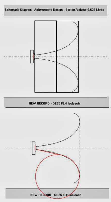
Note that due to this math, you can determine what size of horn you can build by evaluating what sonotubes are available at your local home depot.
For instance, if you can get 12" sonotube, then you can build a LeCleach horn that's 12" deep.
You can also get away with using one half or even one quarter of the sonotube, since the left hand side is conical.
Here is how you can approximate a LeCleach curve quickly and inexpensively.
This might be a good option for people who are too lazy to build molds.
Here's how you do it:
1) First, make the horn in Hornresp, using the standard methodology of simulating a LeCleach curve. (documented in the help file.)
2) I believe you can approximate a LeCleach curve by combining a conical horn with a monster roundover. In the pic above, I am illustrating how to do this. You basically cut the horn right down the middle. The left hand side is the conical side; the right hand side is created with a roundover.
When I say 'monster roundover' I mean it; in the horn above the roundover is a full eighteen centimeters long.
Making the conical section is fairly simple; it can be made with wood and the sides can be calculated in a few minutes. Bill Waslo has a spreadsheet that can calculate conical horns too.
The roundover is a little bit trickier. I am personally using sonotube. For my horn I should be using a 14" sonotube, but 13" was the biggest size I could find at my Home Depot.
Mating the two sides is up to you. I am going to use fiberglass, but even duct tape would work.
Here's the thread where I am documenting the build up of this horn:
http://www.diyaudio.com/forums/multi-way/244508-monster-massive-new-post.html
Note that due to this math, you can determine what size of horn you can build by evaluating what sonotubes are available at your local home depot.
For instance, if you can get 12" sonotube, then you can build a LeCleach horn that's 12" deep.
You can also get away with using one half or even one quarter of the sonotube, since the left hand side is conical.
Last edited:
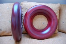
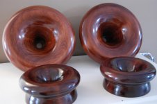
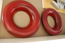
JMLC horns
Some wooden JMLC horns. 🙂
Some wooden JMLC horns. 🙂
Attachments
Last edited:
Speculation
Tube radius need not be larger than 1/8 wavelength of the lowest frequencey to be passed by the horn.
Regards,
WHG
I am using a curve inspired by LeCleach on my latest speaker.
Here is how you can approximate a LeCleach curve quickly and inexpensively.
This might be a good option for people who are too lazy to build molds.
Here's how you do it:
1) First, make the horn in Hornresp, using the standard methodology of simulating a LeCleach curve. (documented in the help file.)
2) I believe you can approximate a LeCleach curve by combining a conical horn with a monster roundover. In the pic above, I am illustrating how to do this. You basically cut the horn right down the middle. The left hand side is the conical side; the right hand side is created with a roundover.
When I say 'monster roundover' I mean it; in the horn above the roundover is a full eighteen centimeters long.
Making the conical section is fairly simple; it can be made with wood and the sides can be calculated in a few minutes. Bill Waslo has a spreadsheet that can calculate conical horns too.
The roundover is a little bit trickier. I am personally using sonotube. For my horn I should be using a 14" sonotube, but 13" was the biggest size I could find at my Home Depot.
Mating the two sides is up to you. I am going to use fiberglass, but even duct tape would work.
Here's the thread where I am documenting the build up of this horn:
http://www.diyaudio.com/forums/multi-way/244508-monster-massive-new-post.html
Note that due to this math, you can determine what size of horn you can build by evaluating what sonotubes are available at your local home depot.
For instance, if you can get 12" sonotube, then you can build a LeCleach horn that's 12" deep.
You can also get away with using one half or even one quarter of the sonotube, since the left hand side is conical.
Tube radius need not be larger than 1/8 wavelength of the lowest frequencey to be passed by the horn.
Regards,
WHG
Is it your company?
Any prototype ready yet for the TH4003?
- Home
- Loudspeakers
- Multi-Way
- Jean Michel on LeCleac'h horns