-with smoothing at only 1/24th, yup - driver (not horn, or rather this horn). The only exception to this that can cause "hash" is less than excellent coupling between driver and horn. But with you.. yeah, HIGHLY unlikely. 😀
Thought I would add that the dip between 3K and 4K is an artifact of the D250P-8 compression driver. It shows up on every horn I've tested the driver on. The ripples in the HF response also show up on all horns. Turning up the smoothing or doing it visually you can see different HF responses on the different horns but the underlying ringing is common.
Best example of ringing, hash, and FR anomalies caused by throat mismatch I have is a pair of Parts-express 12" round waveguides with screw on adapters. First issue is the screw on adapters actually have a reverse taper of 3º with the outlet being smaller than the inlet. Second issue is the throat on the waveguide is too big even for a screw on horn driver let alone the adapter that is smaller than 1".
I took one of the adapters and re-machined the taper to 5.7º to match the Radian 475 drivers. Then after attaching the adapter to the waveguide the waveguide was re-shaped to have a nice smooth transition. This improved the impulse and frequency response but it's still not great.
I'll add the images of before and after in another post.
Last edited:
If you are trying to measure the entrance angle of of a horn you can use a General Tool #17 protractor.
If the measurement arm is cut down to 1/2" or so you can measure the exit angle of CD's that don't have the bug screen right at the exit.
General Tools and Instruments
Thanks Gary! That is very helpful.
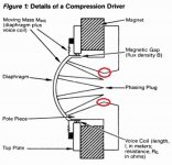
I got the attached picture from the JBL tech note:
http://www.jblpro.com/BackOffice/ProductAttachments/tn_v1n08.pdf
I have highlighted the points where the exit to the driver begins. Will there not be diffraction at those points? Almost all the CDs have this change in angle at the start of the exit. Probably the BMS designs, which have a straight slot, don't have this point.
Attachments
Not sure if this should be in Jean-Michel's thread or Lynn's thread. But as Both have a lot of horn/waveguide info here goes...
OK, after taking a close look at the throat mismatch on the PE waveguides and screw on adapters the differences are not as big as I was expecting. Should be a good data point though.
First a photo of the throats of the horns with the unmodified horn on the left.
Next, the impulse response with the modified horn on top.
Frequency response with modified horn on top
And CSD with un-modified on left
Easiest thing to see is how the frequency response from 15K up drops like a rock on the unmodified horn and there is an extra bump at 6.5K. CSD is cleaner above 15K also. Compared to the JMLC horn everything above 2.5K drops off faster.
Overall, the PE 12" waveguide is not that good, but what did I expect for $12.00...
Gary
OK, after taking a close look at the throat mismatch on the PE waveguides and screw on adapters the differences are not as big as I was expecting. Should be a good data point though.
First a photo of the throats of the horns with the unmodified horn on the left.
An externally hosted image should be here but it was not working when we last tested it.
Next, the impulse response with the modified horn on top.
An externally hosted image should be here but it was not working when we last tested it.
Frequency response with modified horn on top
An externally hosted image should be here but it was not working when we last tested it.
And CSD with un-modified on left
An externally hosted image should be here but it was not working when we last tested it.
Easiest thing to see is how the frequency response from 15K up drops like a rock on the unmodified horn and there is an extra bump at 6.5K. CSD is cleaner above 15K also. Compared to the JMLC horn everything above 2.5K drops off faster.
Overall, the PE 12" waveguide is not that good, but what did I expect for $12.00...
Gary
Impedance plots for the above post.
Gold/yellow is unmodified horn/adapter. Green is modified horn/adapter.
Gold/yellow is unmodified horn/adapter. Green is modified horn/adapter.
An externally hosted image should be here but it was not working when we last tested it.
Thanks for those Gary. I did some similar tests with the Dayton waveguides stock and smoothed using a Selenium driver. The differences were much less than I expected, and never great.
I got the attached picture from the JBL tech note:
http://www.jblpro.com/BackOffice/ProductAttachments/tn_v1n08.pdf
I have highlighted the points where the exit to the driver begins. Will there not be diffraction at those points? Almost all the CDs have this change in angle at the start of the exit. Probably the BMS designs, which have a straight slot, don't have this point.
BUMP
Too soon to bump? I would also like to know this. The angles of the spikes is not exactly straight. Will it matter that much? Maybe the easiest solution if you can actually hear a difference would be to switch to another driver.
I have highlighted the points where the exit to the driver begins. Will there not be diffraction at those points? Almost all the CDs have this change in angle at the start of the exit. Probably the BMS designs, which have a straight slot, don't have this point.
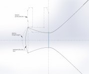
Not to pollute the LeCleac'h thread, but the BMS drivers aren't perfect either, at least not the 4552nd which I have and have taken apart. Here's a drawing I made a while back.......disregard all the weird bending business after the CD throat 🙄
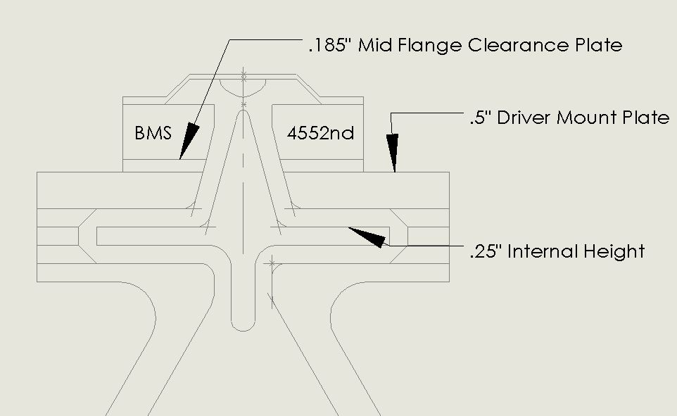
That's about a 26° exit angle. You can see where the throat is straight then sharply changes angle? The straight part of the throat is a guide where a thin wall cylinder attached to the diaphragm/back plate slides in to center the vc in the gap. The "u" shape at the top of the drawing is the phase plug, along with a bunch of radial slots that I didn't draw.....
Whatever is going on at that detail is in the end up to the ear. I tried my Goto S-150 with an twin driver adapter right in the beginning of the throat, adding 5 cm to the end. I noticed more power but a very small lack of clarity compared to a single driver. Driver was FS100W. XO was 200-600Hz. Higher frequencies are probably more sensitive to throat angles since the wavelengths are much shorter.
The throat should start at the phase plug adjacent to the cone. At the points you've marked the pressure from each of the slits should be in phase. The cross sectional area at this point on the horn should be appropriate for the combined pressures from the phase plug, and it afterwards continues the same expansion.http://www.jblpro.com/BackOffice/ProductAttachments/tn_v1n08.pdf
I have highlighted the points where the exit to the driver begins. Will there not be diffraction at those points?
Impedance plots for the above post.
Gold/yellow is unmodified horn/adapter. Green is modified horn/adapter.
Thanks for the measurements, Gary.
Is there really that much improvement though? Those look like significant changes in the throat area you made there. The FR, the all important FR, looks about the same, except above 15 kHz.
The throat should start at the phase plug adjacent to the cone. At the points you've marked the pressure from each of the slits should be in phase. The cross sectional area at this point on the horn should be appropriate for the combined pressures from the phase plug, and it afterwards continues the same expansion.
You are assuming that the horn starts where the phase plug ends. I may be wrong but this is almost never the case. In the JBL diagram, and in the drivers I have seen, this is not the case. The phase plug ends inside the driver and there is an opening with finite length before the exit. The device with no throat would have a 0 degree exit angle, correct?
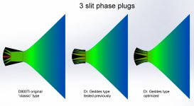
Phase plug.
Something similar to the last figure in jzagaja's post would probably be ideal. Jack, is someone making these drivers?
I can see why this might be important. We want the wavefront to not have any sharp discontinuities in its path. But why don't manufacturers spec this very important parameter? And why don't horns specify it either?
From Gary's and Pano's experience, there doesn't seem to be much impact on FR.
Jack, is someone making these drivers?
Nobody 🙂 I've made similar mod and directivity was smoother especially in 10k-20k region but the driver had strong breakup there. This mod reduces flux in the gap. Difference on FR is academic ;-)
I'd have called it the beginning, not the end but could be a simple misunderstanding. I was idealising, sure, but the point I was making is that the bends you pointed out (WRT diffraction) don't necessarily appear as bends to the wavefront.You are assuming that the horn starts where the phase plug ends.
Hasn't Earl said that the OS waveguide is intended to make use of a plane wave? With a phase plug designed to give a spherical wave at the driver exit, wouldn't you want a conical horn?Phase plug.
Thanks for the measurements, Gary.
Is there really that much improvement though? Those look like significant changes in the throat area you made there. The FR, the all important FR, looks about the same, except above 15 kHz.
I was a bit surprised that that much change in the throat didn't have more influence on the FR. Also interesting was that there were changes in the impedance in the 700Hz to 3Khz range but only very small changes in the FR in that range.
To make things easier to compare, here is an image with 1/6 octave smoothing applied and no offset. Also included in this image is the FR of the D250P on one of the 1K JMLC horns I've turned.
Red is the unmodified 12" PE waveguide + adapter, blue is the modified 12" PE waveguide + adapter and green is the 1K JMLC horn. The same PE D250P-8 driver is used for all 3 measurements.
An externally hosted image should be here but it was not working when we last tested it.
Just for grins here is an image of the back side of the 1K JMLC horn turned from layers of Baltic birch.
An externally hosted image should be here but it was not working when we last tested it.
- Home
- Loudspeakers
- Multi-Way
- Jean Michel on LeCleac'h horns