Hiraga's Le Pré-Pré revisited
under
Prepre (Aufholverstarker) fur MC-Tonabnehmer in Basisschaltung - wie Hiraga MC Preamp - als Fertiggerat; Hersteller gesucht - Phono - allgemein - Analogue Audio Association
(post #12) there are two circuits based on Hiraga's Le Pré-Pré.
Who have heard both modern versions ?
under
Prepre (Aufholverstarker) fur MC-Tonabnehmer in Basisschaltung - wie Hiraga MC Preamp - als Fertiggerat; Hersteller gesucht - Phono - allgemein - Analogue Audio Association
(post #12) there are two circuits based on Hiraga's Le Pré-Pré.
Who have heard both modern versions ?
Attachments
Last edited:
Le PrePre - LTSPICE model
Hi,
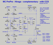
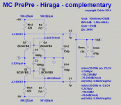
I just made a diagram in LTSPICE, for the P-version, using the 2SA1613 instead of the 2SA737
It is the 2SB737 that I use (bought at the Maison de l'Audiophile) but I have no model for it; it has the same Rbb of 2 ohm. A very important design element I recollect.
View attachment Hiraga LePrePre P-version 2SA1316 - 2SB737 .asc
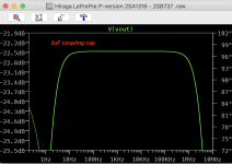
the curve

Amplifies 36 dB.
Have fun.
Hi,
I just made a diagram in LTSPICE, for the P-version, using the 2SA1613 instead of the 2SA737
It is the 2SB737 that I use (bought at the Maison de l'Audiophile) but I have no model for it; it has the same Rbb of 2 ohm. A very important design element I recollect.
View attachment Hiraga LePrePre P-version 2SA1316 - 2SB737 .asc
the curve

Amplifies 36 dB.
Have fun.
I am planning on building the so called Symmetric Hiraga MC amplifier. PCB is almost ready, but I would like to have opinions on grounding scheme. As you can see, at the moment GND is separated on the PCB between the PSU and the MC amp.
Could the grounds be connected at J2?
Should I split ground in the MC section and connect "ouput ground" to PSU ground?
Thanks!
🙂 morten


Could the grounds be connected at J2?
Should I split ground in the MC section and connect "ouput ground" to PSU ground?
Thanks!
🙂 morten
check out this thread:
I don't like this topology without DC protection and prefer a topology with electrolytic capacitors between moving coil cartridge coil and MC amp input as used in Mark Levinson's JC-1DC. Schematics are to find in PDF attachments from post #8 under
There are two methods of coupling the moving coil cartridge to the prepre input:
1) AC coupling about a capacitor
2) DC coupling (without a capacitor)
By AC coupling I have lack in quality cause additional capacitor device in series to the moving coils, but by DC coupling I risk a damage of both internal cartridge moving coils in case of an error in the head amp circuit (frontend).
Therefore the question:
How much current and voltage is acceptable at the moving coils without the risc of damage from internal coil winding?
Second question: What kind of dc protection are there without...
- tiefbassuebertr
- Replies: 30
- Forum: Analogue Source
Both versions are for operating without mains power supply - just two secondary D-cells are in use.
What is the difference ?
BTW - the mains supply version uses the additional term "AC"
The difference is the year of release - the suffix "DC" means a newer series (release 1976) than the older series without that suffix (release already 1974) go to
ハイファイ堂メールマガジン
Who know the difference between the gain stage circuits of this both versions ?
The schematic of the JC-1DC (potted version), which I have create some years ago, you will find in post #8 below.
Maybe there is also a schematic...
- tiefbassuebertr
- Replies: 33
- Forum: Analogue Source

