where do you see a bjt? there is only a regular NPN transistor (MPSa42).
The initial switching frequency is 100khz, as the sevice manual says.
I have the data sheet of the MC74ACT14AN and the vcc is 7v max.
Yes, having some sort of ttl could bring the voltage to a safer condition for the mosfets, i will try all this anyway with fresh parts.
Do you have any suggestions for a mosfet?
Is the IRFZ4x serie worth a try?
I got plenty of IRFZ44.
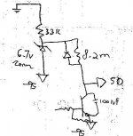
There is realy something wrong with the schematic for the SD input, there is a zener diode tied to v+, a 33k to it tied to v-, and the 8.2mohm resistor is connected to the tied of the zener and the resistor so on should read there +vcc-Vzener, while it should have -vcc+Vzener to get around 6.2v to the SD input, referenced to -vcc.
If i take measurements on the circuit while the module is not there, i read 88.2 volts.
The zener and the resistor just needs to be swaped...😕
There is UVLO writen around this part of the schematic.
thanks.
The initial switching frequency is 100khz, as the sevice manual says.
I have the data sheet of the MC74ACT14AN and the vcc is 7v max.
Yes, having some sort of ttl could bring the voltage to a safer condition for the mosfets, i will try all this anyway with fresh parts.
Do you have any suggestions for a mosfet?
Is the IRFZ4x serie worth a try?
I got plenty of IRFZ44.
There is realy something wrong with the schematic for the SD input, there is a zener diode tied to v+, a 33k to it tied to v-, and the 8.2mohm resistor is connected to the tied of the zener and the resistor so on should read there +vcc-Vzener, while it should have -vcc+Vzener to get around 6.2v to the SD input, referenced to -vcc.
If i take measurements on the circuit while the module is not there, i read 88.2 volts.
The zener and the resistor just needs to be swaped...😕
There is UVLO writen around this part of the schematic.
thanks.
Someone will have to explain me something:
look at the schematic.
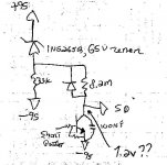
This is what the original schematic shows. the zener diode is a 65volt one.
SD input of the AMI module should never be more than 7 volts, referenced to -95v.
I am getting 6.2 volts with the schematic is show you now, so it is "ok"
i dont get it, i was expecting to see +95-65(Vzener)=30v, referenced to ground, but something like 125 volts if referenced to -95v😕
The 8.2mohm resistor is responsible to charge the capacitor at the input of the schmitt trigger inside the AMI module, as a "soft start" ?
look at the schematic.
This is what the original schematic shows. the zener diode is a 65volt one.
SD input of the AMI module should never be more than 7 volts, referenced to -95v.
I am getting 6.2 volts with the schematic is show you now, so it is "ok"
i dont get it, i was expecting to see +95-65(Vzener)=30v, referenced to ground, but something like 125 volts if referenced to -95v😕
The 8.2mohm resistor is responsible to charge the capacitor at the input of the schmitt trigger inside the AMI module, as a "soft start" ?
Attachments

pat allen said:where do you see a bjt? there is only a regular NPN transistor (MPSa42).
The initial switching frequency is 100khz, as the sevice manual says.
I have the data sheet of the MC74ACT14AN and the vcc is 7v max.
Yes, having some sort of ttl could bring the voltage to a safer condition for the mosfets, i will try all this anyway with fresh parts.
Do you have any suggestions for a mosfet?
Is the IRFZ4x serie worth a try?
I got plenty of IRFZ44.
There is realy something wrong with the schematic for the SD input, there is a zener diode tied to v+, a 33k to it tied to v-, and the 8.2mohm resistor is connected to the tied of the zener and the resistor so on should read there +vcc-Vzener, while it should have -vcc+Vzener to get around 6.2v to the SD input, referenced to -vcc.
If i take measurements on the circuit while the module is not there, i read 88.2 volts.
The zener and the resistor just needs to be swaped...😕
There is UVLO writen around this part of the schematic.
thanks.
Hi, The MPSA42 NPN is a BJT.
I checked the data sheet again, it does say VCC MAX =7Vdc. But that's the smoke point! "Maximum ratings beyond which damage to the device may occure"
While the "Recommended MAX values" are VCC= 5.5Vdc.
Even if you wanted to push your luck with the chips and run them close to 7 volts VCC, it still isn't really enough to drive a regular mosfet as a switch comfortably, and if you dont' turn them fully on they'll run hot and might burn.
The speed of the 10V cmos family would likely be just fine at ten times more than the switching frequency, but they still have a much higher threshold which might complicate things, or degrade performance, so I would stick with the ACT family and use a regulated 5Volts for VCC.
You can not use an IRFZ44 with this, It is only a 60V part, it isn't a logic level mosfet either (Vth is 2 to 4 volts), it is only starting to think about turning at that level of gate drive, and needs to be driven up to at least 8 min, 10 comfortably, to get the lowest on resistance.
Have a look at the link I gave you in my last post, it is a 200V part like the current device is, which you need because with +-95 volt rails, they have to block 2*95, with some safety margin preferably), and handles more current than the mosfets that were in there. They will be fully turned on with 5Volts gate drive, they seem a much better choice than what was in there.
The beauty of this is, if you use those mosfets, you don't need to redesign anything, can still use the same PCB, with all the other parts staying the same!! Just swap mosfets, replace all components that got burnt, and improve the supplies like you were going to (regulated to ~5.1 not 7). I'd find some way to heatsink the mosfets before you test it too, the epoxy was doing that job before, if you fire it up with no cooling they'll smoke pretty quick.
I figure that'll work fine unless some other problem we haven't spotted yet creeps up on you.
I really can't make out that whole SD thing, maybe someone else can help with that.
Regards
Hi, you are right, i didnt look deep enough about the bjt, my mistake, and for the irfz, i didnt rememeber that they were low voltage, now i know why i have so much of them, i have used them for a pwm power supply for a car amp.
I never meant to drive the 74act beyond theirs limits, and it is one of my goal to "protect" them. Building a 5 volt regulator could be very cheap and effective, if i can find those FQA mosfets, i usualy buy my parts at Digikey, they dont have it 🙁
I will build some prototype tomorrow, with all the mods i plan to do.
That will be fun, its my first digital amp project !
One last question if you dont mind, i am wondering why the psu is so high in voltage, the current capability of the tranfo seems to be very small, the 95v will never to all thru the sub. They claims a 250w rms for this set-up.
Could it be smart to lower the voltage and raising up the amps?
I have looked at the ZaP pulse modules, those modules needs a lot of amp to deliver the advertised wattage, with far lower voltage...could it be only due to %efficiency ?
JBL=65%
Zap=+95%
I am just wondering where i can improve 😀 ...
thanks for all the good information you give me.
You can improve by ripping it all out and buying that plate amp I linked you to awhile back 🙂
I have no idea how they calculated that power rating, but expect it to be 90% BS. By my math the woofer would need to be over 250Ohms to get around 250W RMS sine power.
Know what the impedance of it actually is?
Anyway I'll spend a few coffee's thinking about that SD thing, I still think it is just a pre charge control circuit, if it puts the oscillator in stand by, there's some voodoo happening.
Oh, you might be able to get some samples of that mosfet direct from fairchild. If you fish through what Digikey has you may find other "logic level" mosfets, but they might be rare, I haven't seen too many logic level power fets, fairchild make really good mosfets anyway too.
Got any ideas how you can cool them while you test?
Regards
Hi, i finaly made this sh*t work on a breadboard.
The basics seems to work, i am able to get sounds out of it with 15 volts rails.
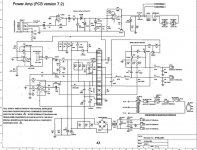
I have redone the schematic with power logic. There is still some parts that i dont got the value.
C3 and C4 are not on my proto and it seems to work good, i did try some caps in there, from 10p to 100n, no changes. Duno value.
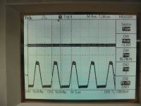
I have a signal generator and a techtronics scope and can see the actual sine signal if it gets distorted or bad,...it is fairly good for now until cliping wich occcurs at close to vcc.
C6 also bugs me, it seems that it just limit the free bandwith of the osccilation, even if it oscillates at only ~20khz for now, cant make it go to the 100khz it should. C7 also seems confusing, i have replaced it with a resistor because the op amp was not able to lower its output enough to trigger the first shmitt trigger.
So C7 is a 4.7k for now. C2 also is an unknow cap value, i have put a 0,01 for now and it works.
SD when high ground the emitter of Q3 thru d8, enabling the circuit to self oscillate. It is part of the muting circuit and soft shut down, it enable the amp to stop without a thump.
the upper shmitt trigger is powered thru D6, when the signal input is low, it charges c1.
the overall circuit is also very instable and very dependant of the output filtering stage. as soon as i put inductor/caps, the free oscillating frequency drops a lot.
Let me know what you think of the missing value components.
The basics seems to work, i am able to get sounds out of it with 15 volts rails.
I have redone the schematic with power logic. There is still some parts that i dont got the value.
C3 and C4 are not on my proto and it seems to work good, i did try some caps in there, from 10p to 100n, no changes. Duno value.
I have a signal generator and a techtronics scope and can see the actual sine signal if it gets distorted or bad,...it is fairly good for now until cliping wich occcurs at close to vcc.
C6 also bugs me, it seems that it just limit the free bandwith of the osccilation, even if it oscillates at only ~20khz for now, cant make it go to the 100khz it should. C7 also seems confusing, i have replaced it with a resistor because the op amp was not able to lower its output enough to trigger the first shmitt trigger.
So C7 is a 4.7k for now. C2 also is an unknow cap value, i have put a 0,01 for now and it works.
SD when high ground the emitter of Q3 thru d8, enabling the circuit to self oscillate. It is part of the muting circuit and soft shut down, it enable the amp to stop without a thump.
the upper shmitt trigger is powered thru D6, when the signal input is low, it charges c1.
the overall circuit is also very instable and very dependant of the output filtering stage. as soon as i put inductor/caps, the free oscillating frequency drops a lot.
Let me know what you think of the missing value components.
Attachments
**** what a simple Class D amp  My class d am has alot more components, but my amp is intended for fullrange tho.
My class d am has alot more components, but my amp is intended for fullrange tho.Please, take note that the schematic is the AMI module only, there is several other components on the circuit, see one of the post above for the other schematic.
It work full range for now.
It work full range for now.
Still simpler than my amp, this one: http://www.medicom.bang-olufsen.com/sw2014.asp Full H-brigde tho.
Yes, but no close to the quality of yours, you work for Bang Olufsen ?
This is still something JBL did sold, again,
Duno how this sub cost new...
I have changed the power supply on my bread board from 12v rail to 30 v rail, and the mosfets are irf840 wich are not very suited for the task. There is no heat sink as well on them
I managed to get 25v pk to pk on a 4 ohm load, with some begining of audible cliping.
I am stumped. It smell bad too, the mosfet are glow red 😀 .
This is roughly 75wrms i think.
I will order some better mosfets and will build a pcb, there is some emi that i can see on my scope.
This begin to be a fun project, i have tweaked the caps and now i got around 100khz free running frequency.
It does work 😱
cheers !!!
Hi, what are you final cap values?
I would expect the mosfets to glow red and burn out very fast. This is why we want to use logic level mosfets, so they turn fully on with such low drive voltage. Otherwise they'll be passing full current with a high Ron and heat like crazy. Some of your values might need to change once you put them on a PCB because it will have less stray junk to worry about. You could try doing a dual layer PCB and use the top layer as a dedicated ground plane, would help with the noise.
Tekko, are you sharing your design with us?? It's not like you can sell it anyway..
Tekko, are you sharing your design with us?? It's not like you can sell it anyway..
good one !!!😀
Surpisingly, i can play music quite loud and they dont burn...i dont care because i have tons of them, we use this mosfet here in one of our product so...
Final caps are: c6 is a 10p, c2 is a 0,047u, no c3 and c4.
There is a missing one at the emitter of q3, that goes to -95v, is a 0,1uf for now.
R7 is a 330 ohm.
C5 is a 0,1uf
R10 is a 1kohm, i found that r10 ajust the symetry of the wave, i get the best results with 1k, and a 0,01uf in parralel on it, it also removes some noise at very low frequency (5hz and less 😀 )
There is still something that i have not figured the why of, is the voltage that flows thru D6. In order to make this amp work, i have to send dedicated voltage thru it, so figure for now that D6 is a 1k resistor connected to +vcc. It work fine as is.
Feedback resistor is still a 56k.
Mosfet are now ordered (the ones you suggested me)
tanks.
I just meant that the B&O module has alot of ic´s and components on it. and your jbl thing only had like 2-3 ic´s that was only smitt triggers and a quad opamp ic.
pat allen said:Tekko, are you sharing your design with us?? It's not like you can sell it anyway..
good one !!!😀
Surpisingly, i can play music quite loud and they dont burn...i dont care because i have tons of them, we use this mosfet here in one of our product so...
Final caps are: c6 is a 10p, c2 is a 0,047u, no c3 and c4.
There is a missing one at the emitter of q3, that goes to -95v, is a 0,1uf for now.
R7 is a 330 ohm.
C5 is a 0,1uf
R10 is a 1kohm, i found that r10 ajust the symetry of the wave, i get the best results with 1k, and a 0,01uf in parralel on it, it also removes some noise at very low frequency (5hz and less 😀 )
There is still something that i have not figured the why of, is the voltage that flows thru D6. In order to make this amp work, i have to send dedicated voltage thru it, so figure for now that D6 is a 1k resistor connected to +vcc. It work fine as is.
Feedback resistor is still a 56k.
Mosfet are now ordered (the ones you suggested me)
tanks.
Yeh, as long as they dont' melt into your proto board and touch each other
Your earlier posted seemed to confirmed how that whole BJT mess seems to work to charge the bootstrap capacitor..
But it won't do it without an additional resistor?? hmm is the turn on delay working as it should?
It's OK to add an aditional resistor to VCC to the bootstrap cap, but I hope you didn't actually "replace" D6 diode for a resistor! If you're going to leave that resistor there it would be a good idea to add another resistor after the cap tied to the negative rail, and with enough of a delay you can make them bigger as well.
Hope those mosfets work well for you.
got a new thing...
It seems that the bandwith is very narrow. Like from 20hz to 80 hz.
I got a 250uh inductor coil with 2x 2.2uf caps as the only filtering devices at its output.
It feels like when i am getting the resonant frequency of the sub (8 inch subwoofer, 4 ohm from a infinity amplified subwoofer), that it got the best results. I can throw 22v pk to pk thru it without having distortion, and it occurs at 33hz. The mosfets dont get hot at all.
If i change my frequency generator up or down, then i can hear some cliping as if i was hearing the mosfets turning on and off.
Any ideas? it only occurs at high levels, the lower it is, the better the bandwith is.
I am looking at the bjt and if the signals are not overlaped.
thanks.
- Home
- Amplifiers
- Class D
- JBL PB12 subwoofer, Class D amp, dead.