Hallo
I want to pick up the idea of JAT with his downsized JAT501. he called this small amp EZ amp. Target is lower cost , less parts and good TDH and good power ratings.
its 4 years ago and i want to restart this idea. target was 35W at 8R and 50W at 4R. he tried in his videos with 28V rail and To-220 darlington transistors. at the beginning he blow some parts and finaly he get it.
mandatory is to use a bigger heatsink and mount the bias spreader (BD139) directly at one of the output transistor.
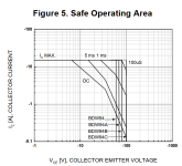
in the video you can follow his way that he was thinking that this Darlington are as strong as the bigger transistors like 2SC5200( To-264) but you have to watch the SOA.
please remember that the target is as less parts and cheap as possible (darlington for 80 cent) to get a working amp. TO-220 housing have less heat transportation to the heat sink and so you have to watch out the heat sink. 20WATT is the maximum power what you can handle with this housing. think about the LM1875 or UTC2050 chipamps.
I personally looked at this SOA of the darlingtons. Yes it is for 30V for me critial if you want to have 50W or so. i looked at a lot of darlingtons and normally you get at the DC diagramm of SOA just 2amps max or maybe 3 amps. this is the rason why i coose just 21V rail for the first try.
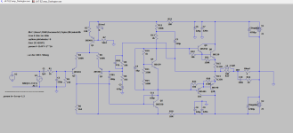
i have done a LTspice with an older schematic so i used what i have to go on. i sum all comments at the videos and some ideas of the JAT501 builder thread here (red LED) the amp is working. for other FFT, OLG i need your help please. any other suggestions are very welcome. thx. CCS should have about 1,4mA to have enough current for other stages. i found no darlingtons in my LT spice so i re build it discrete.
with 1,9Vp at the input and 4R load it give us 16,8Vp at the output and therefore about 35WATT.
i try my first KICcad file since nearly 3 year - so sorry i am not an expert. its not finished and i guess i did a strange layout. but lets check first in LTSpice if this amp is working well. the kicad is not really update with some resistor values but that is the next step after working amp.
videos:
video 1
video 2
video 3
video 4
video 5
darlington: available - not so easy because a lot of darlingtons are now obsolete:
BDW94C - BDW93C...cost about 1 euro
look at the SOA and think about margin of current with capacitive loads.
if you want to have more power then you have to use more darlingtons to be on the save side. see at AB100 amp or AA9MD here in this forum.
this is not the target here.
kr
chris
variant 1: use bigger output tranistors as cheap as possible and sziklair pair like JAT501. actually TIP3055/TIP2955 are the cheapest /bigger ops transistors i found. 90W
TIP41 shold be better? TIP41 comment
very nice amp by minek with 3x TIP3055/2955 - minek´s power amp with 3x TIP3055/2955
any other 2SA1491/2SC3855 - 100W ISCSEMI can do...
variant2: use old 2SD2390/ 2SB1560 second hand from old AV amps. actually available but not cheap
edit:
17.1.2025 final schemtaic at post 20
with Darlington BDW93C TO-220 housing with 22Vrail / 4R 35WATT.
BOM at post 21
18.1.2025 changed schematic after square wave response simulation. - post 22 -JAT EZ amp done! 😉
21.1.2025 post 31 -LT spice file to play around
post 39 - Gerber file done by Peter - Kleinhorn. thx
08.02.205 add mineks amp to variant 1
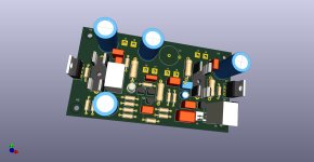
2.4.2025 final amp build at post 133
final amp with measurements posts before
24.04.2025 post 135
last version LTspice and amp schematic
update the last LTspice file -last version 6 and last schematic
ideas for next version
I want to pick up the idea of JAT with his downsized JAT501. he called this small amp EZ amp. Target is lower cost , less parts and good TDH and good power ratings.
its 4 years ago and i want to restart this idea. target was 35W at 8R and 50W at 4R. he tried in his videos with 28V rail and To-220 darlington transistors. at the beginning he blow some parts and finaly he get it.
mandatory is to use a bigger heatsink and mount the bias spreader (BD139) directly at one of the output transistor.
in the video you can follow his way that he was thinking that this Darlington are as strong as the bigger transistors like 2SC5200( To-264) but you have to watch the SOA.
please remember that the target is as less parts and cheap as possible (darlington for 80 cent) to get a working amp. TO-220 housing have less heat transportation to the heat sink and so you have to watch out the heat sink. 20WATT is the maximum power what you can handle with this housing. think about the LM1875 or UTC2050 chipamps.
I personally looked at this SOA of the darlingtons. Yes it is for 30V for me critial if you want to have 50W or so. i looked at a lot of darlingtons and normally you get at the DC diagramm of SOA just 2amps max or maybe 3 amps. this is the rason why i coose just 21V rail for the first try.
i have done a LTspice with an older schematic so i used what i have to go on. i sum all comments at the videos and some ideas of the JAT501 builder thread here (red LED) the amp is working. for other FFT, OLG i need your help please. any other suggestions are very welcome. thx. CCS should have about 1,4mA to have enough current for other stages. i found no darlingtons in my LT spice so i re build it discrete.
with 1,9Vp at the input and 4R load it give us 16,8Vp at the output and therefore about 35WATT.
i try my first KICcad file since nearly 3 year - so sorry i am not an expert. its not finished and i guess i did a strange layout. but lets check first in LTSpice if this amp is working well. the kicad is not really update with some resistor values but that is the next step after working amp.
videos:
video 1
video 2
video 3
video 4
video 5
darlington: available - not so easy because a lot of darlingtons are now obsolete:
BDW94C - BDW93C...cost about 1 euro
look at the SOA and think about margin of current with capacitive loads.
if you want to have more power then you have to use more darlingtons to be on the save side. see at AB100 amp or AA9MD here in this forum.
this is not the target here.
kr
chris
variant 1: use bigger output tranistors as cheap as possible and sziklair pair like JAT501. actually TIP3055/TIP2955 are the cheapest /bigger ops transistors i found. 90W
TIP41 shold be better? TIP41 comment
very nice amp by minek with 3x TIP3055/2955 - minek´s power amp with 3x TIP3055/2955
any other 2SA1491/2SC3855 - 100W ISCSEMI can do...
variant2: use old 2SD2390/ 2SB1560 second hand from old AV amps. actually available but not cheap
edit:
17.1.2025 final schemtaic at post 20
with Darlington BDW93C TO-220 housing with 22Vrail / 4R 35WATT.
BOM at post 21
18.1.2025 changed schematic after square wave response simulation. - post 22 -JAT EZ amp done! 😉
21.1.2025 post 31 -LT spice file to play around
post 39 - Gerber file done by Peter - Kleinhorn. thx
08.02.205 add mineks amp to variant 1
2.4.2025 final amp build at post 133
final amp with measurements posts before
24.04.2025 post 135
last version LTspice and amp schematic
update the last LTspice file -last version 6 and last schematic
ideas for next version
Attachments

Last edited:

BD139/140 are fine for these voltages. Those are not power transistors though, those are drivers.
2SC1943/5200 are real power transistors rather generic and dirt cheap.
Actually can just use TO-220 as well same old MJE15028/29 at these voltages.
No wonder he blew up transistor, just plain wrong to start. Nobody around here cares to be " careful"
No such thing, use the right transistors. No issue.
Otherwise this is the same old recycled topology seen a million times.
Not trying to sound degrading actually, it has been nit picked to death. So just let people build it the way they want.
Until it blows up or they need help.
R6 looks too high, the whole differential looks like it getting blasted with to much current.
probably has marginal stability. most people dont use degen, is actually good to use.
Think im seeing it though, because he had to add it to make it stable.
Simple differential, Simple 2nd gain stage. The performance and " low distortion" already pre determined.
Not really that low, same old same old.
21 volt rails, can just drive a power stage with a 5534 opamp it will do .0006% to .001 distortion.
This one is done at .01%
It is good that he made this videos and sparked your interest, great fun.
Gotta say i was obsessed with low cost ultimate transistor too in the beginning for some reason.
Finally realized the difference between 1 dollar transistor or 2 dollar transistor isnt even a hamburger.
Why worry the power supply and case will be 100x that much.
Last edited:
Thank you white Dragon.
Yes i use the wrong ops transistors because i use what i get fast out of the models.
So your comment is to do another amp it is funny but waste of time.
Kr Chris
Yes i use the wrong ops transistors because i use what i get fast out of the models.
So your comment is to do another amp it is funny but waste of time.
Kr Chris
Hi Whitedragon
your comment:
R6 looks too high, the whole differential looks like it getting blasted with to much current.
probably has marginal stability. most people dont use degen, is actually good to use.
Think im seeing it though, because he had to add it to make it stable.
i am unsure what you mean with CCS istoo much because normally (AA14 amp or Bob cordell book chapter 3) a CCS has about 1mA for the differential pair.
my idea was that i use 1,4mA because have enough curent for stabilize the R6 voltage (yes it is too high) to hold the Q5 open + current to charge the miller cap at Q5 (100p is maybe too high).
i set the CCS to 1mA and changed the R6 to 1k
how can i do it right? can i see this at the LT spice file?
thx
chris
Attachments
It was a quick over look current source seemed higher.
1 to 2 ma yes is correct.
Second Gain stage is T092 so likely only 1ma to yes 1.5ma needed
Ideal value for R6 will balance differential currents.
Assuming temperatures are set to average 22 to 27c
Change this value for lowest DC offset at output.
For simple topology like this with no current mirror
people will tolerate almost 30 to 45mv DC offset at output.
Using 1% resistor or E96 tolerance values you should
be able to bring down to respectable 1 to 10mv
909 , 931, 953, 976, 988 etc etc
Use this chart as value guide to use in sim
For example of mentioned 5534 circuit, I made a new thread.
Fun circuits I figured nobody cares about, but hey there it is lol.
For realistic sim download your chosen Darlington file and import model in spice.
I had plenty of fun with those BDW94/95
I thought they stopped making them, maybe wrong.
Powerful yes 80 watt for T0220 when most are around 40 watt
For discrete Darlington also download file and import model
Suggest typical higher ft transistor
MJE150x yes tyipcal 40 watt D44 will be 80 watt
High speed switching devices / BDW considered low speed
MJE15028, MJE15030 (NPN),MJE15029, MJE15031 (PNP)
or D44VH10(NPN),D45VH10 (PNP)
OnSemi has huge library of spice models to expand your options.
Last edited:
Awesome Whitedragon. Thanks for your time. maybe it is anoying for you but i want to go through that.
Last edited:
just adjust R6 it is now good symetrie at R4, R5,
R6 is 1k65 E96
dc ofsett about 47mV
current is IR4=507uA and IR5=502uA

R6 is 1k65 E96
dc ofsett about 47mV
current is IR4=507uA and IR5=502uA
lookas okay is set the VBe multiplier better -it was to less voltage -s so the "darlingtons" doesnt open enough.
R13 =2k2 -so i have about 2,9V.
max power looks okay with 1,9vpp input at 4R

R13 =2k2 -so i have about 2,9V.
max power looks okay with 1,9vpp input at 4R
i set the bias more at the OPS
Q8 about 140mA, Q7 126mA
so the VBE R10 is now 1k54 to spread the VBe a bit more (3,1V), VAS has Q4 8mA and Q5 VAS is about 10mA (i think during power this couls be the bootle neck--> getting too hot...about 400mW)
i re-config the differential :
input R6 to 1k74 to get nearly identical idel current at both input transistors Q2,Q3.
DC offset is now 47mV
Last edited:
how to setup the Class AB -zero crossing, distortion -bias?
as you can see at the setup above i havee a symmetrical output voltag into 4R.fine. but the zero crossing ...is that okay for simulation?


as you can see at the setup above i havee a symmetrical output voltag into 4R.fine. but the zero crossing ...is that okay for simulation?
DC offset like post 14.
R6 is now 2k15 and DC offset is now 3mV. that is fine.
idle current at the OPS Q7, Q8 is more symmetrical and about 130mA.
still the VAS current is at 10mA (too much?).

R6 is now 2k15 and DC offset is now 3mV. that is fine.
idle current at the OPS Q7, Q8 is more symmetrical and about 130mA.
still the VAS current is at 10mA (too much?).
look at the VAS Q5:
Q5 has about 11mA idele current and a voltage swing at max power (1,9Vpp input) of 38,2Vp. so that is about 420mWATT. i guess with heatsink...?
TO-92 heat sink
or is it a must to go up to the drivers TO126?
but they have "just" about 100hfe- toshiba have about 220hfe (TTC004B_Q)
PS: i did a short sim. instead of Q5 2N5551 i use a BD139...it works fine. same gain 18,9dB and it looks okay. so the complete job is done by the darlingtons...or? DC offset now -5mV
Last edited:
Hi
i need time to understand that i have to use the corect symbol that fit to the model of BW93C. now it is ready.
file is called DArlington _BDW93C.
DC offset 1.47mV. bias current is about 107/108mA.
R6 and R10 have to be recalculated to get this datas.
power at 4r is the same 16,838Vp ---> 35WATT at 4R.
have fun
chris
Attachments
- Home
- Amplifiers
- Solid State
- JAT EZ amp - idea by John Audio Tech