Here is a better schematic that follows what I think to be a Janszen wiring diagram format. You were correct, the top diodes were backwards. Ha! It is difficult to identify which way they go since I am looking at component parts mirror imaged from the wiring trace on the back both left to right and also the similar left side parts to right side parts. A double whammy for me.
Peter
Peter
Attachments
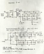
Thanks for the additional board pic. Your schematic now looks correct. 
Either the diode orientation is incorrect or the voltage label is incorrect...I'm not sure which.
You can see an example of the polarity error contained in some of the factory diagrams. The orientation of the diode would produce +1100V, not -1100V....In a note on his website, young Janszen mentioned the factory wiring diagrams got the polarity defined incorrectly.
Either the diode orientation is incorrect or the voltage label is incorrect...I'm not sure which.
Attachments
I installed a 2kHz low pass filter on both speakers since the new 10” woofers seemed to go to 5kHz; however, someone on another forum said to run the speakers for some time to “burn in” the capacitors on the crossovers. I’m doing that now.
I also added a second set of speaker terminals for the woofers so I can swap the woofer polarity (phase) quickly by just reversing the banana plugs.
We shall see how it goes (or hear),
Peter
I also added a second set of speaker terminals for the woofers so I can swap the woofer polarity (phase) quickly by just reversing the banana plugs.
We shall see how it goes (or hear),
Peter