 Thread split from: Tube amp high-voltage delay
Thanks Mark - never saw that AR amp! Seems like a nice touch.
The controller is really a no-brainer; after switching the HV on it goes to sleep, switching everything off, its clocks, timers, what have you. It just becomes a blob of dead silicon sipping away a few tens of microamps.
In The Netherlands we have a saying that means something like: 'unknown makes unloved' 😎
Here on my bench I have a completed design of a HV regulator for tube amps. Less than 1mV noise, no sagging under load, light, low heat. No need for additional power supply.
A single R sets the output anywhere between 0V and 580V. A single R sets the current limit to anywhere between 5mA and 1A. Fully overload and short-circuit protected. A tube amp's wet dream.
But I am hesitant to publish it because it contains - gasp - an opamp ...
Jan

Hi Jan,
I actually would be very interested in that 🙂
We have a lot of mains voltage fluctuations here, which makes setting bias current on my opto bias regulated EL84PP quite time-consuming, and I‘m also concerned of overvoltage conditions during start-up, when the tubes are not drawing enough current yet ... 😛
I‘m using my external power supply alternating for the EL84 amp or for my Aikido pre-amp, and an easy way of re-setting it for the different amps would also be appreciated. Right now, B+ for the power amp is done unregulated, but for the Aikido of course regulated.
Regards, Claas
Hi Jan,
First of all thanks for sharing your delay circuit.
I would like to know more about your hv powersupply. This sounds very promising indeed. I have a transformer 440V 800mA to make a nice psu.
Regards, Gerrit
First of all thanks for sharing your delay circuit.
I would like to know more about your hv powersupply. This sounds very promising indeed. I have a transformer 440V 800mA to make a nice psu.
Regards, Gerrit
Hi Jan,
for the EL84PP it would be B+ of 320V and 175mA, or alternatively, up to 340V and let‘s say 150mA.
For the Aikido, my implementation runs with 250V B+ and up to 80mA of current, depending on tubes used.
Best regards, Claas
for the EL84PP it would be B+ of 320V and 175mA, or alternatively, up to 340V and let‘s say 150mA.
For the Aikido, my implementation runs with 250V B+ and up to 80mA of current, depending on tubes used.
Best regards, Claas
Hi Jan,
First of all thanks for sharing your delay circuit.
I would like to know more about your hv powersupply. This sounds very promising indeed. I have a transformer 440V 800mA to make a nice psu.
Regards, Gerrit
Hi Gerrit,
Currently the regulator can handle 600V absolute max input. With your 440V that will reach, when rectified, higher than that.
I can probably find some parts for a higher voltage, let me check that out.
Jan
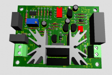
This is how it will look.
Jan
Hi Jan, looking very good and that board looks small enough to fit 🙂
Thanks and best regards, Claas
Jan,
I’m trying to understand the hv regulator circuit. It’s impressive and I would like to build one, if I can find the right components. Do you have any thoughts on a PCB?
Regards, Gerrit
I’m trying to understand the hv regulator circuit. It’s impressive and I would like to build one, if I can find the right components. Do you have any thoughts on a PCB?
Regards, Gerrit
Trying to understand as well. And I don‘t get circuit diagram and picture from #43 completely together yet ... 😱
Jan,
I’m trying to understand the hv regulator circuit. It’s impressive and I would like to build one, if I can find the right components. Do you have any thoughts on a PCB?
Regards, Gerrit
I have some PCBs available, as well as some of the HV parts.
On the 3D view you see three TO220 devices, but you would use only two in an actual circuit. But there are two possible positions for the pass device, either on the on-board heatsink for disspations up to 6 or 7 watts, or on the edge of the board for mounting on a chassis or larger heatsink. There is a note to that on the schematic.
Jan
Last edited:
Trying to understand as well. And I don‘t get circuit diagram and picture from #43 completely together yet ... 😱
The error amplifier, the AD8031, drives the gate of the pass device.
That opamp gets two inputs. One is the output voltage, on the inv input. The other is the reference voltage, on the non-inv input. The difference between them drives the gate up or down.
Jan
Hi Jan,
I’m interested in a PCB + some essential parts (Conrad for the rest?).
What can you offer?
Regards, Gerrit
I’m interested in a PCB + some essential parts (Conrad for the rest?).
What can you offer?
Regards, Gerrit
Hmmm ...
Reference voltage is provided by U1, the LT3092 ?
And the circuitry around Q8 steps down the difference between Vin and Vout to a safe voltage range for the op-amp ?
So I guess the regulator doesn‘t limit Vraw from climbing up too high when there‘s no load yet (tubes not fully heated up / bias servo still at too negative grid voltage). I have a PSU that‘s cLCC (or LCC), and without load the voltage keeps climbing. For this, I probably would combine the regulator with your HV delay circuit, right?
Regards, Claas
The PCB I have, and the ref current source LM3092 (I can put that on the board if you are uncomfortable with SMD), the HV depletion mode IXTP08N100D2, the AD8031, the pass MOSFET FDP12N60NZ.
Let's say € 30 plus shipping.
R11 has to be selected depending on the necessary Vout at about 0.58V per kOhm. So for instance, for 250V, R11 should be ~430k. You can adjust the Vout +/-20% with VR1. Note that R11 must be selected for the full output voltage. Conrad or Mouser should have it.
I might also have a few of the HV film caps, C3, C4 and C6 but I need to check. I think they are about € 2,00 each.
Jan
Hmmm ...
Reference voltage is provided by U1, the LT3092 ?
And the circuitry around Q8 steps down the difference between Vin and Vout to a safe voltage range for the op-amp ?
So I guess the regulator doesn‘t limit Vraw from climbing up too high when there‘s no load yet (tubes not fully heated up / bias servo still at too negative grid voltage). I have a PSU that‘s cLCC (or LCC), and without load the voltage keeps climbing. For this, I probably would combine the regulator with your HV delay circuit, right?
Regards, Claas
The LT3092 is configured as a current source, about 580uA, and develops the reference voltage across R11.
A main feature is that the whole regulator circuit floats on Vout so there's no issue with dividing down high voltage. Also, it means that the loop gain is always the same no matter the Vout, so it is stable for any Vout.
Q8 etc steals some current from Vin to develop a small supply voltage for the opamp and the LT3092. By using a very low supply current opamp (typ 800uA) and a high brightness LED in series with the LT3092, the whole reg circuit runs at just a few mA.
That also means however that you must have a load that takes at least 3mA or so, you should not run it open load. But anything you hang off it will surely take more than 3mA.
Jan
Hi Jan,
I would like to buy a PCB. I’m not familiar with SMD soldering, my Weller soldering station dates from before SMD. So if you could put it on the board that would be great. I’ll take the other parts from you as well, if possible, as far as you have them available. I see that the IXTP08N100D2 is not available from Conrad.
How can I make the payment to you? If necessary you can mail me at info AT winvis DOT nl.
Regards, Gerrit
Hi Jan,
I would like to buy a PCB. I’m not familiar with SMD soldering, my Weller soldering station dates from before SMD. So if you could put it on the board that would be great. I’ll take the other parts from you as well, if possible, as far as you have them available. I see that the IXTP08N100D2 is not available from Conrad.
How can I make the payment to you? If necessary you can mail me at info AT winvis DOT nl.
Regards, Gerrit
YGM.
I think I got the entire stock of the IXPT08N100D2 from Mouser a few months ago. ;-)
Jan
I‘d like a board as well. Thank you very much for offering, and I would like to go with your offer of PCB and parts as spelled out in the first paragraph of #16.
My soldering station is simple as well, but I tried SMD soldering with the tiny JFETs for the BAF2018 line stage, and didn’t find it too bad. It actually was easier than expected. So I‘ll try this one, too 🙂
Would you contact me via PM for PayPal instructions or similar ?
Thanks in advance, best regards, Claas
- Home
- Amplifiers
- Tubes / Valves
- Jan's HV regulator