But I am hesitant to publish it because it contains - gasp - an opamp ...
As far as sound goes the opamp is a minor issue compared to the series topology. Never liked it, no matter what the pass element, even when using a valve.
Obviously according to my taste, ears, systems.
As far as sound goes the opamp is a minor issue compared to the series topology. Never liked it, no matter what the pass element, even when using a valve.
Obviously according to my taste, ears, systems.
Under which circumstances did you use the serial regulator you did not appreciate? Was it a low PSRR circuit of a voltage amplifier, a high current final, SE or PP?
As far as regulators go, my preference is also with the shunt type, but one has to be practical w.r.t. dissipation...
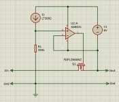
I just found out that earlier I posted an older schematic. The actual schematic and the PCB I have available does have a 12V zener across G-S of the pass device ...
I'm getting too old for this stuff 😎
Jan
I'm getting too old for this stuff 😎
Jan
but one has to be practical w.r.t. dissipation...
Indeed. I have never attempted to supply a valve power amp with regulated voltage, so yes, if one absolutely has to do it, a series regulator is the only practical option.
The question of regulation by itself is interesting. Personally, i have no interest in using regulation as a substitute for a good passive power supply. My interest goes only as far as regulation can bring sonic improvements additional to what a pile of chokes and caps can do. In this context i find shunt regulation beneficial. Series can perhaps make things lighter and cheaper and pacify an engineering god, but as far as music reproduction goes i hear only negatives.
Nice circuit! I am very interested, i just wanted to share this application note from IXYS about linear operation of fet's.
And recommend a different pass device, in case your going to run the supply hard (high input output differential voltage) for instance as a experimenting supply.
IXTP15N50L2
https://www.ixys.com/Documents/AppNotes/IXAN0068.pdf
And recommend a different pass device, in case your going to run the supply hard (high input output differential voltage) for instance as a experimenting supply.
IXTP15N50L2
https://www.ixys.com/Documents/AppNotes/IXAN0068.pdf
Nice circuit Jan. I am interested in a board and parts as well.
One question, as show in your first schematic. The reference current through R11 looks like it will only drop 127.6V across R11, so the output voltage is one diode drop (D3) less at ~127V.
Is this correct for the values shown in your circuit?
One question, as show in your first schematic. The reference current through R11 looks like it will only drop 127.6V across R11, so the output voltage is one diode drop (D3) less at ~127V.
Is this correct for the values shown in your circuit?
Nice circuit! I am very interested, i just wanted to share this application note from IXYS about linear operation of fet's.
And recommend a different pass device, in case your going to run the supply hard (high input output differential voltage) for instance as a experimenting supply.
IXTP15N50L2
https://www.ixys.com/Documents/AppNotes/IXAN0068.pdf
Thanks for that app note! There are several devices SOA-specified that are of interest. I selected the FDP12N600NZ because it has a SOA of 400mA at 600V. This is important for short-circuit protection, because at that condition the full input voltage (max 600V in this case) is across the device.
In fact, I placed a TO247 footprint on the PCB in case I find a device for even higher current/voltage,but no luck so far.
The IXTB30N100L (600V 500mA), IXTN62N50L (400V 750mA) and IXTK22N100L (800V 300mA) are of intererst.
By the way, what they call electro-thermal instability is also known in the industry as the Spirito effect, after the guy who discovered it.
Jan
Last edited:
Nice circuit Jan. I am interested in a board and parts as well.
One question, as show in your first schematic. The reference current through R11 looks like it will only drop 127.6V across R11, so the output voltage is one diode drop (D3) less at ~127V.
Is this correct for the values shown in your circuit?
I don't think so. The ref goes to the non-inverting input through a 100R stopper R only. The diode is there for reverse protection at start-up.
But that schematic is not the final one. I will take the suggestion to set up a Group Buy and post the final circuit there.
Jan
Last edited:
Group Buy is here: https://www.diyaudio.com/forums/group-buys/344165-buy-jans-voltage-regulator.html#post5949320
Documentation is here: T-reg HV regulator | Linear Audio NL
Jan
Documentation is here: T-reg HV regulator | Linear Audio NL
Jan
Hi Jan, do you think ferrite beads inserted on both legs of D3 would help noise rejection at higher frequency?
Very nice regulator, but I think it could benefit from a better opamp than the AD8031: at 80MHz, the GBW looks a bit limited.
At most, you will be able to supply a 27MHz CB PA without a single bypass cap, but to achieve the same feat with a FM transmitter, or a band III transmitter, something like 800MHz or 1GHz looks more reasonable.
Clever circuit anyway....
At most, you will be able to supply a 27MHz CB PA without a single bypass cap, but to achieve the same feat with a FM transmitter, or a band III transmitter, something like 800MHz or 1GHz looks more reasonable.
Clever circuit anyway....
Last edited:
Hi Jan, do you think ferrite beads inserted on both legs of D3 would help noise rejection at higher frequency?
I don't think so. In normal operation, that D3 is not active, as if it isn't there. Both sides are at the same level, for a few mV.
Jan
Thanks Jan. I asked because A side of D3 connects to clean reference and the K side connects to the ouput which may still contains residual RF and other switching noises. Was wondering about possible RF noise leaking through diode's stray C.
Thanks Jan. I asked because A side of D3 connects to clean reference and the K side connects to the ouput which may still contains residual RF and other switching noises. Was wondering about possible RF noise leaking through diode's stray C.
Why would the output have RF and switching noises? Where would that come from then?
Jan
- Home
- Amplifiers
- Tubes / Valves
- Jan's HV regulator