hello. how does this compare to your original one, jmo1? i do not need voltage gain 😀 only after good sound 😀
If you don't want gain, you'll need to go with the original JMo or the original-original Szekeres.
i go with original jmo. i like jfet input 😀 i think it will sound better than szekeres.
my better= more dynamic, more 2h.
am i correct thinking that yours will be better than szekeres? 😀
my better= more dynamic, more 2h.
am i correct thinking that yours will be better than szekeres? 😀
Yes, since it is not a good idea to drive a power MOSFET directly from a volume potentiometer. That's my reasoning at least.
yes, very smart design. already know it will sound good, hehe.
maybe i go with mk2, because maybe the bjt also add pleasant distortion 😀
maybe i go with mk2, because maybe the bjt also add pleasant distortion 😀
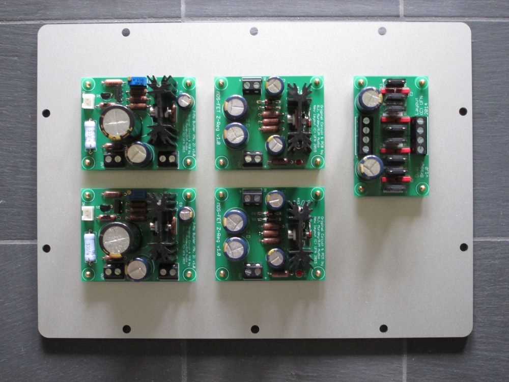
Obviously still some wiring missing, but since I have tested the boards and they are working I though I'd show off anyway - my J-Mo clone is ready 😀
I thought the design looked interesting but wanted to try out a different PCB layout (sorry Richard 🙂 ) to be able to use different parts. I managed to shrink the boards a bit in the process, but that wasn't the primary purpose. I have just tested the amp very briefly in a bench setup, but it seems sound quite good.
/U.
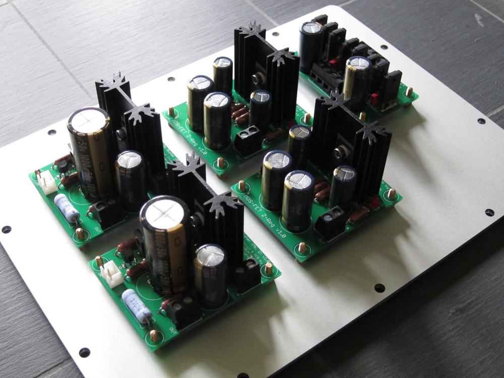
Pics:
I thought the design looked interesting but wanted to try out a different PCB layout (sorry Richard 🙂 ) to be able to use different parts. I managed to shrink the boards a bit in the process, but that wasn't the primary purpose. I have just tested the amp very briefly in a bench setup, but it seems sound quite good.
/U.
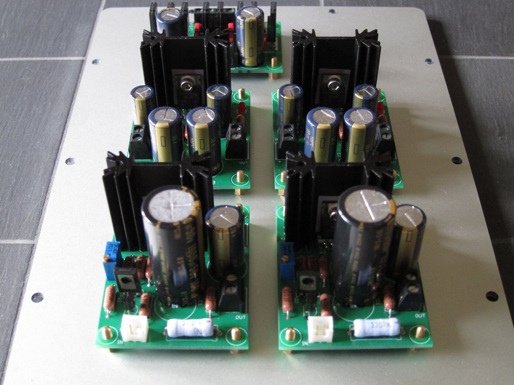
Pics:
Very nice, and no need to apologize: you haven't changed the name, or claimed the circuit as your own.
I'm surprised you didn't put the M-reg and J-Mo and diodes on the same board. It would have saved you having to wire a bunch of interconnects... screw terminals are not ideal as far as long-term reliability is concerned.
I'm surprised you didn't put the M-reg and J-Mo and diodes on the same board. It would have saved you having to wire a bunch of interconnects... screw terminals are not ideal as far as long-term reliability is concerned.
Thanks Richard. I didn't actually think about combining it all on one PCB, but I guess that could be done - for the complete monoblock experience 🙂
/U.
/U.
No idea, all I have done so far is confirm that no smoke escapes when the boards are powered up and that it can actually play music 😀
/U.
/U.
How does it sound compared to Green Borbely?
Google throws me a blank. Which circuit are you talking about?
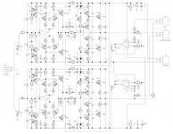
Ah, that one. I remember it, but Boberly's site seems to have vanished so I'm copying the circuit from the ebay listing of the guy you got the boards from. I don't know who did what, but it is a similar to the Gilmore amp, though with a diamond buffer output stage. I recently touched on something similar.
Anyhow, should make for an interesting comparison. Push pull vs. single ended circuits and all that.
Anyhow, should make for an interesting comparison. Push pull vs. single ended circuits and all that.
Attachments
hello, is it possible use bd140 and 2n5485 (or is it 5480?) instead? that all parts they have in my stop.
Sure, the 5485 has a slightly lower Vgs off, so you may want to decrease R2 a little to compensate.
Vgs off of about -1 V. It won't work very well. Try to use jfets with Vgsoff about -(2~4) V.
The J-Mo II circuit is not suited for gains over 5x.
The J-Mo II circuit is not suited for gains over 5x.
sound is... amazing! 😀
i worry first because cap output. but sound extreme detail and clear. very pleasant, too. thank you 😀
i would like ask again, tho. the cap, i use 220uf with low imp phone, and as preamp. this affect frequency? even as preamp higher value cap better frequency response? thank you again 😀
and is it possible increase h2 distortion with change resistor?
Last edited by a moderator:
As a preamp, you could use a much smaller value, a 2 uF film cap for example. Larger values will not improve the frequency response unless you are driving a 600 ohm input or something. 220 uF is fine for most headphones, though I invite you to experiment a little: larger values can subjectively sound more "bassy", smaller values more lean or fast, so personal preference and matching the sonic characteristics of the headphone comes into play.
Basically, the higher the circuit gain the higher the distortion. The exact relationship between the resistor values and the performance is complicated as the bias currents as well as the gain are affected. It's someting that's best examined under simulation with LTSpice.
Basically, the higher the circuit gain the higher the distortion. The exact relationship between the resistor values and the performance is complicated as the bias currents as well as the gain are affected. It's someting that's best examined under simulation with LTSpice.
- Status
- Not open for further replies.
- Home
- Amplifiers
- Headphone Systems
- J-Mo Mk II headphone amplifier