Greg,
I would remove 2SC3421, BD139, MJE340 and their complementary pair from the list.
Hi WuYit,
I know they aren't ideal but people do use them. Notice their poor ranking.
regards
Greg,
I would remove 2SC3421, BD139, MJE340 and their complementary pair from the list.
by comparing between various datasheets of BD139 I note, that this one from SIEMENS offers the most informations.
BD139 Datasheet pdf - NPN SILICON TRANSISTORS - SGS Thomson Microelectronics
SMD-Versions of BD1397bd140 are this:
http://www.nxp.com/documents/data_sheet/BC639_BCP56_BCX56.pdf
http://www.nxp.com/documents/data_sheet/BC640_BCP53_BCX53.pdf
Last edited:
Thank you tiefbassuebertr, but it does not change the fact that BD139 is basically a switch transistor, unsuitable for voltage amplification. It is better for current amplification although I would prefer 2SD669, 2SC1162 (Hitachi) or 2SC2824, 2SC3421 (Toshiba).
the BD135-140 series make excellent linear amplifiers.
Use the BD series where it's parameters suit the circuit operating conditions.
As a low voltage amplifier driver? or a cascoded and EFed VAS? or as a cascode for a VAS? etc.
Maybe I should re-phrase that second sentence. Only use the BD series when the linear application suits it's parameters.
Use the BD series where it's parameters suit the circuit operating conditions.
As a low voltage amplifier driver? or a cascoded and EFed VAS? or as a cascode for a VAS? etc.
Maybe I should re-phrase that second sentence. Only use the BD series when the linear application suits it's parameters.
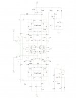
Well, I suppose one would consider 2N7002V and BSS84V as 'switching transistors'. This does not bar them from use in linear amplifier applications. The output of this amplifier is very linear......and very fast.🙂 This is the 'voltage amplifier' section of my modular balanced EC mosfet amp. It's like 4 seperate amplifers with active common bias, that uses source feedback and phase lag compensation, COG 0.5 - 1pf, in each quadrant. It seems like a ridiculous value for compensation caps, but with a reasonable PCB layout (layout is very important for this circuit), the circuit will not be stable without them.😛 With a balanced input, this circuit drives the two seperate EC output stages that are bridged across the speaker, and in terms of current gain, require no more than 8uA of drive current from each side of this circuit.
Attachments
Last edited:
EDIT..... that is an older drawing, it has been established that there should be no feedback around the output stage follower circuits back to this circuit, so disregard the FB nodes.
Greg,
advocating inappropriate types does not boost the confidence for the presentation.
Suggestion: the transit frequency for all devices could be designated at a chosen practical value of current for easier overview.
advocating inappropriate types does not boost the confidence for the presentation.
Suggestion: the transit frequency for all devices could be designated at a chosen practical value of current for easier overview.
Well I feel out of place! Just started using the Fairchild KSC2690A and complement but then I use a fair amount of bias current there- 60ma. I do not care for high Z as that brings to many other problems.
I see some very nice transistors suggested by others too. Will check some out.
Also I do not care for cascode. While the frequency response is wider the delay through the circuit is longer. For wider bandwidth others have suggested using a common base stage instead of common emitter. Seems like a better idea than cascode if global feedback is used because common base has less delay. Of course any particular circuit has advantages and disadvantages.
One more thing... do not like to see all those obsolete devices shown. I used to use the MPS-U60 and U10 but those are long gone as are many devices listed in this thread! How am I to try those parts out?
Interesting thread. Thanks to everyone.
Last edited:
I thought common base was the same as cascode?
We should ask him, if he sees any difference in between CB and Cascode😀
Exactly. Also the MPS-U60 and U10 are the most obsolete of them all.I thought common base was the same as cascode?
Okay look here on a thread by Soekris http://www.diyaudio.com/forums/atta...dback-production-ready-soekris_bip190_sch.pdf with the common base wired directly to the input comparator.
For the current to voltage converter stage there is only one transistor wired common base by Soekris and every cascode I ever saw uses two transistors. Cascode has one transistor as the input with an output current from the collector connected to the emitter of the "upper" transistor which is referred to as the cascode being wired common base. Maybe one transistor compared two transistors is the same? Certainly two transistors has more delay. What is popular for VAS is common emitter with one transistor. I was simply suggesting connecting that one transistor as common base so cleverly as Soekris has. I admire his work by the way. A very sensible amp in many ways.
MPS-U10 is the oldest. Do I get a prize? Obsolete is just really not worthwhile except as a point of reference from a historical perspective. How about RCA40410 and 40409? Haha! This is a joke so please at least smile.
🙂=SUM
My 2 useless cents
For your kind information,
The configuration shown in your link is known as "FOLDED CASCODE"😀😀.
The drain of Mosfet Q13 connects to emitter of Q11
&
The drain of Mosfet Q12 goes through wilson current mirror formed by Q7-Q10-Q20 and finally goes to emitter of Q21.😉
This is a common Topology, nothing surprising in it.
Certainly not....!!!😛😀
Okay look here on a thread by Soekris diyAudio with the common base wired directly to the input comparator.
For your kind information,
The configuration shown in your link is known as "FOLDED CASCODE"😀😀.
The drain of Mosfet Q13 connects to emitter of Q11
&
The drain of Mosfet Q12 goes through wilson current mirror formed by Q7-Q10-Q20 and finally goes to emitter of Q21.😉
This is a common Topology, nothing surprising in it.
Do I get a prize?
Certainly not....!!!😛😀
Last edited:
sumaudioguy,
a common base current to voltage converter stage should consist of just one device like the second stage, but very unfortunately and inconsistently, the input cascode made up of a common gate amplifier, a MOSFET(!), to perform the same task.
a common base current to voltage converter stage should consist of just one device like the second stage, but very unfortunately and inconsistently, the input cascode made up of a common gate amplifier, a MOSFET(!), to perform the same task.
Thanks you guys for giving me a great idea!! Simulations say WOW for what that is worth. Going to build one real soon and see what it really does.
Thanks again!
Thanks again!
Greg,
advocating inappropriate types does not boost the confidence for the presentation.
Suggestion: the transit frequency for all devices could be designated at a chosen practical value of current for easier overview.
Hi WuYit,
Thanks for the suggestion. I have been meaning to write the recommended selection criteria. Some of the reference threads do have suggestions for selecting a good one.
I just noticed that I do have a this warning.
WARNING: Some of the more generic transistors (e.g. BD139 and MJE340) have incomplete datasheets and also have multiple manufacturers with varying specifications. Use caution when selecting these components.
regards
- Home
- Amplifiers
- Solid State
- It's 2010 and what's your fav VAS transistor?