How are you going to power it? Jap ac is 100, in us its 120, often even higher.View attachment 1162560View attachment 1162561View attachment 1162562View attachment 1162563View attachment 1162564
Waiting for shipping
Hitachi ha-500f
Might be the worst sounding vfet amp according to information in forums.
I will verify that.
I also heard modding will make huge improvements. I will test that also.
Is there a voltage selector inside? I do not see it so far.
Are you going to use step down trafo? Or variac? Or replace the transformer? Or just go for it and overload the caps and risk blowing something?

Ha-500f arrived, I listened to it breifly, feel nothing special. Connected to main in , left pre-amp out of the equation, no big difference. My initial impression is not as clear and smooth as ba-1000. But that is not my conclusion might be wrong feeling. I will compare them and keep posting.
Drain to drain output is really slow on the turnoff due to the 5.6k resistor. It wastes more power at high output due to cross conduction.
I am going to try a similar thing with 2sc5200
Using 4.7 ohm shutoff and IRF9610.
The other configuration is KSC3503 > IRFP240
I want to see if BJT to MOS or MOS to BJT is better.
I am going to try a similar thing with 2sc5200
Using 4.7 ohm shutoff and IRF9610.
The other configuration is KSC3503 > IRFP240
I want to see if BJT to MOS or MOS to BJT is better.
WhiteDragon pointed me to another more contemporary simulator (TINA TI & thanks!).what schematic can mimic jfet or sit transistor????????
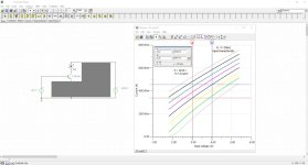
Played a little with it last weekend to change a BD139 into a triode output.
VS1 [1.8-5.4], 8 steps, VS2 [4-40], 8 steps:
μ = S * Ri = 117.4 mA/V * 81.6 ohm = 9.6
Instead of concave curves (according to my other Spice simulator), the are convex!?!
But most important is the equal distance between the curves, yields less distortion.
Grayed out is the simple trick, obviously. Patent is pending.
Attachments

when the pattent approved???? 1 year later????WhiteDragon pointed me to another more contemporary simulator (TINA TI & thanks!).
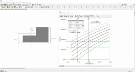
Played a little with it last weekend to change a BD139 into a triode output.
VS1 [1.8-5.4], 8 steps, VS2 [4-40], 8 steps:
μ = S * Ri = 117.4 mA/V * 81.6 ohm = 9.6
Instead of concave curves (according to my other Spice simulator), the are convex!?!
But most important is the equal distance between the curves, yields less distortion.
Grayed out is the simple trick, obviously. Patent is pending.
A year won't surprise me, and I'm very sorry I cannot disclose this now. I know it would be liked very much.
With the TINE TI simulating software it is easy to build models (based on real ss devices!) for various active elements.
In preparation: Vfets (2SK60/2SJ18), real tube replacements (E88CC) with a high voltage mosfet, a complementary 'p-channel tube', maybe a p-channel sit, a two stage non-nfb main amplifier (drains to the output), various types made from bjt, j- & mosfet.
When I have a working curve tracer, I shall post a short clip with a breadboard to show the magic happening in the future.
If the patent is approved, it will be disclosed.
Patent apps can take a long time. Part of that is due to the searches required to check thousands of publications and other patents for prior art to ensure that ideas are novel. You would have to do this yourself if you didn't employ a patent agent.
Did you consider the old jfet valve replacements that were offered in the 1960's? I don't recall any details specifically except for a couple of ads in the mags indicating plug-in valve replacements using jfet in some sort of cascode configuration. Never saw a circuit for one.
Did you consider the old jfet valve replacements that were offered in the 1960's? I don't recall any details specifically except for a couple of ads in the mags indicating plug-in valve replacements using jfet in some sort of cascode configuration. Never saw a circuit for one.
WhiteDragon pointed me to another more contemporary simulator (TINA TI & thanks!).
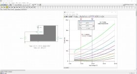
Played a little with it last weekend to change a BD139 into a triode output.
VS1 [1.8-5.4], 8 steps, VS2 [4-40], 8 steps:
μ = S * Ri = 117.4 mA/V * 81.6 ohm = 9.6
Instead of concave curves (according to my other Spice simulator), the are convex!?!
But most important is the equal distance between the curves, yields less distortion.
Grayed out is the simple trick, obviously. Patent is pending.
Good to see your having fun.
Voltage and especially current major factors.
But otherwise with some devices frequency and temperature.
Another benefit with Tina since temperature is easily changed
with the models including more thermal characteristics.
likewise noise. And be able to quickly graph results
at different temp / freq
far as finding the magic with BJT
at higher frequency and temp is where I found challenges
Thanks again WD! And indeed fun.
But it runs on modern pc's only, not on my old fruit machine, nor on a vmwared w2k on it, not on a wined Linux MX19 machine either.
I get a w10 laptop from my employer soon, so from then onwards zapping forward again.
The circuit is temperature stable, it will slightly drift a bit, even if only bjt's are involved.
On Solid State Poetry:Cool, but will there be any side effect by introduce additional elements?
There are three singles:
common emitter, common base and common collector (follower).
They run with some resistors.
There are five compounds (better then 'combo's'):
the differential and the current mirror
the Darlington and the Sziklai (named to their inventors)
and the cascode.
They all run with some resistors.
The poor cascode is alone.
I found it's match, and runs with three resistors.
All specs from the involved active elements (bjt / jfet / mosfet) are valid.
I cannot behold why this does not already exists for ages.
It's not the idea that can be patented, but the application (-s) only.Patent apps can take a long time. Part of that is due to the searches required to check thousands of publications and other patents for prior art to ensure that ideas are novel. You would have to do this yourself if you didn't employ a patent agent.
Did you consider the old jfet valve replacements that were offered in the 1960's? I don't recall any details specifically except for a couple of ads in the mags indicating plug-in valve replacements using jfet in some sort of cascode configuration. Never saw a circuit for one.
And as it fits on nearly every existing current application, the field is endless.
I'm not near the point to break up, but it's on my mind.
Better sell it right away to a big manufacturer (any one of them watching here? -> pm me!)
I've seen these ads a time ago, but I got the impression the replacements were not doing any triode-trick. Just a j-fet and a high voltage cascode (+sleek heatsink) on top, rendering it in a 'degraded' pentode. That is not the way.
In that time, progress was forward only. I had to go back beyond that era to retrieve the original way of thinking when vacuum triodes ruled.
It all happened when the second and third grid were added. Everybody forgot or was blinded. The electronic paradise was about to commence.
My teeth started falling out of my mouth by the 'Merlin-distance' only. You need to understand superposition completely to get it in view. Then... the shock.
Don't expect too much from the patent process. I gave up on the patent office years ago, as well the idea that big business will give you the time of day for one.

Did you make comparisons, build/listen to, or simulate amplifiers with and without your modified transistors ?
Only some compounds to test on cheap curve tracers (affirmed):
BC550C-BC550C: ok; BF245A-BC550C: ok; 2N7000-2N7000: ok; 2N5460-BC560C: ok
A change to purchase a Tektronics CT failed: the seller died (I think) and the device is nowhere.
Building a CT (Elektor Dec 89) is hindered by flaws and things. Lots of frustrations.
Personal matters and the job requires most time (divorce, taxes, dressed tenders for 2025, stent, cough... more?)
I had the idea of modifying a Hiraga into the ss-triode version, but that is postponed for now.
The idea now is to design a full symmetrical two-stage amp, first stage like the Hiraga input (no cascode) outputting towards the rails, second stage like the 4650/5650 drain2drain output. Nowhere e-degen. Not sure if nfb is needed, so openloop / low gain first. Mu per stage is around 10 though (yields into 200x gain).
Anyone having a CT for sale? NWEur.
I'm a digital zero...
Better have the elektor ct fixed.
No idea where I left the compounds on my workbench.
I'll make a few new ones on chips of protoboard and post some pictures of them (single sided only!).
...
Found them: in the Peak DCA75 curve tracer box!
Better have the elektor ct fixed.
No idea where I left the compounds on my workbench.
I'll make a few new ones on chips of protoboard and post some pictures of them (single sided only!).
...
Found them: in the Peak DCA75 curve tracer box!
- Home
- Amplifiers
- Solid State
- Is VFet an internet influencer thing that makes no sense at all?